Switching power supply circuit and switching power supply

A switching power supply circuit and circuit technology, applied in the direction of high-efficiency power electronic conversion, electrical components, regulating electrical variables, etc., can solve the problems of easy overloading of output power, low efficiency of switching power supply circuits, etc., to reduce the volume of filter capacitors, avoid overload, The effect of improving efficiency

Inactive Publication Date: 2020-02-04
KAI HUI ELECTRONICS CO LTD GUANGZHOU
View PDF6 Cites 1 Cited by
  • Summary
  • Abstract
  • Description
  • Claims
  • Application Information

AI Technical Summary

Problems solved by technology

[0004] In order to solve the technical problems that the efficiency of the existing switching power supply circuit is not high an...

Method used


Image

  • Switching power supply circuit and switching power supply
  • Switching power supply circuit and switching power supply
  • Switching power supply circuit and switching power supply

Examples


Embodiment 1

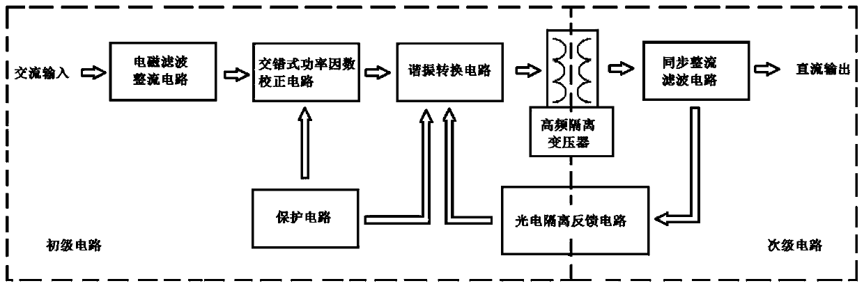
[0044] see figure 1 , this embodiment provides a switching power supply circuit, which includes a primary circuit and a secondary circuit. Among them, the primary circuit is used to filter, correct and convert the externally input AC input to generate a high-frequency square wave signal, while the secondary circuit is used to rectify the high-frequency square wave signal and feed back the rectification result to the resonant conversion circuit to adjust its output signal.

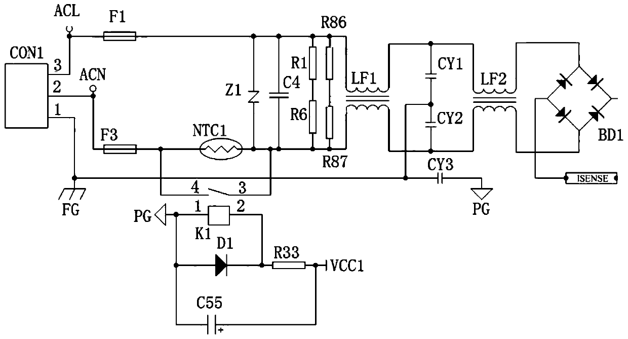
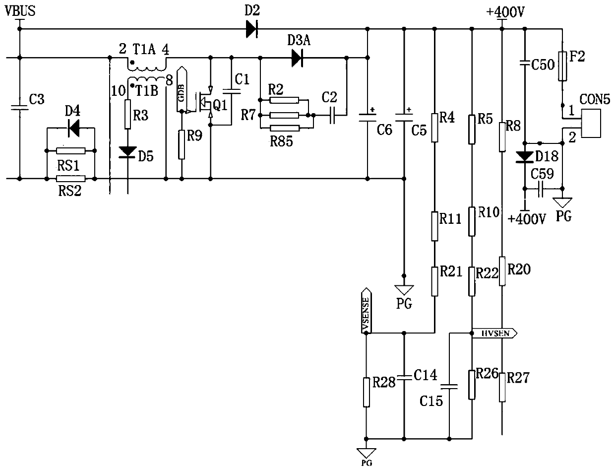
[0045] The primary circuit includes an electromagnetic filter rectifier circuit, an interleaved power factor correction circuit and a resonant conversion circuit. The electromagnetic filter and rectifier circuit is used to filter the AC input to suppress the common mode noise from it, and generate a pulsating DC signal that is transmitted to the interleaved power factor correction circuit. The interleaved power factor correction circuit is used to correct the power factor of the pulsating DC signal, and m...

Embodiment 2

[0072] see Figure 9 , this embodiment provides a switching power supply circuit, on the basis of Embodiment 1, an auxiliary power supply circuit is added to the circuit. Among them, the auxiliary power circuit belongs to the primary circuit, and includes auxiliary power chip U2 MD12H, resistors R69, R70, capacitors C20, C21, C22, C26, diodes D9, D10, D13, D31, DZ1, inductor L2, interface TS1. In this embodiment, pin 1 and pin 2 of the auxiliary power chip U2 are connected, and are connected to the negative pole of capacitor C22, one end of capacitor C21, one end of capacitor C20, one end of inductor L2, and the negative poles of diodes D13 and D31. The pin 3 of the auxiliary power supply chip U2 is connected to the other end of the capacitor C21 and the positive pole of the diode DZ1, the pin 4 is connected to the negative pole of the diode D9 and the positive pole of the capacitor C22, and the pin 5 is connected to the pin 6, pin 7, Pin 8 is connected and connected to a pre...

Embodiment 3

[0074] see Figure 10, this embodiment provides a switching power supply circuit, which adds a lightning protection circuit on the basis of Embodiment 1. The lightning protection circuit is arranged at the front end of the electromagnetic filter rectifier circuit and is used as a part of the primary circuit. It can use the existing lightning protection unit. In this embodiment, only a lightning protection circuit is provided, but in other embodiments it can also be Use other circuit configurations. The lightning protection circuit includes varistors MOV1, MOV2, MOV3 and fuses F4, F5, F6, FDG. One end of the fuse F4 is connected to the pin 3 of the interface CON1, and the other end is connected to one end of the varistor MOV3. One end of the fuse F5 is connected to one end of the fuse F4, and the other end is connected to one end of the varistor MOV1. The other end of MOV1 is connected with one end of FDG and one end of varistor MOV2. The other end of the varistor MOV2 is c...


PUM


Abstract

The invention discloses a switching power supply circuit and a switching power supply. The circuit comprises a primary circuit and a secondary circuit. The primary circuit comprises an electromagneticfiltering and rectifying circuit, an interleaved power factor correction circuit, a resonant conversion circuit and a protection circuit, wherein the electromagnetic filtering and rectifying circuitfilters and rectifies the alternating current input to generate a pulsating direct current signal, the interleaved power factor correction circuit converts the pulsating direct current signal into a direct current level and performs power factor correction at the same time, the resonant conversion circuit carries out high-frequency switching on the direct-current level so as to convert the direct-current level into a high-frequency square wave signal, and the protection circuit is responsible for detecting and protecting the primary circuit. The secondary circuit comprises a photoelectric isolation feedback circuit and a synchronous rectification and filtering circuit. The high-frequency square wave signal is coupled by the high-frequency isolation transformer, rectified and filtered in the secondary synchronous rectification and filtering circuit, and finally output in a direct-current manner. The photoelectric isolation feedback circuit is used for sampling direct current output andfeeding back to the resonant conversion circuit. According to the invention, closed-loop control and overload protection are achieved, the circuit is protected on the one hand, and the direct currentoutput can be stabilized on the other hand so as to avoid damage to a carrier.

Description

technical field [0001] The invention relates to a power supply circuit in the technical field of circuits, in particular to a switching power supply circuit, and also to a switching power supply of the circuit. Background technique [0002] A switching power supply is a high-frequency power conversion device and a type of power supply. The function of the switching power supply is to convert a level of voltage into the voltage or current required by the user through different forms of architecture. The input of a switching power supply is mostly AC power (such as mains) or DC power, and the output is mostly equipment that requires DC power, such as a personal computer, and the switching power supply converts the voltage and current between the two. [0003] The switching power supply circuit generally consists of a main circuit, a control circuit, a detection circuit, and an auxiliary power supply. Among them, the main circuit limits the impact current, and filters the clu...

Claims


Application Information

Patent Timeline
IPC IPC(8): H02M7/217H02M3/335H02M1/32H02M1/42H02M1/44
CPCH02M1/32H02M1/4241H02M1/44H02M3/33592H02M7/217H02M1/0058Y02B70/10
Inventor 李骞王慧
Owner KAI HUI ELECTRONICS CO LTD GUANGZHOU
Why Eureka
Try Eureka