An environment-friendly boiler pressure vessel waste heat recovery device and its working method

A waste heat recovery device and boiler pressure technology, which is applied to heat storage equipment, indirect heat exchangers, heat exchanger types, etc., can solve problems such as inability to achieve, waste of waste heat resources on the inner wall of boiler pressure vessels, and single recovery of waste heat recovery devices. , to achieve the effect of enhancing the recycling effect

Active Publication Date: 2020-11-24
合肥化机装备制造有限公司
View PDF11 Cites 0 Cited by
  • Summary
  • Abstract
  • Description
  • Claims
  • Application Information

AI Technical Summary

Problems solved by technology

[0005] Aiming at the deficiencies of the prior art, the present invention provides an environment-friendly boiler pressure vessel waste heat recovery device and its working method, which solves the problem that the waste heat recovery effect of the existing waste heat recovery method is poor and cannot perform all-round waste heat recovery on the boiler pressure vessel. Recycling only recovers waste heat from boiler waste slag, so that the waste heat resources on the inner wall of the boiler pressure vessel are still wasted. At the same time, the existing waste heat recovery device has a relatively single recovery object, which cannot realize waste heat recovery for liquid, gaseous and solid waste, and cannot achieve The purpose of comprehensive waste heat recovery for boiler pressure vessels, so that it is impossible to achieve sufficient waste heat recovery through boiler pressure vessels to achieve the purpose of energy saving and environmental protection

Method used


Image

  • An environment-friendly boiler pressure vessel waste heat recovery device and its working method
  • An environment-friendly boiler pressure vessel waste heat recovery device and its working method
  • An environment-friendly boiler pressure vessel waste heat recovery device and its working method

Examples


Embodiment Construction

[0033] The following will clearly and completely describe the technical solutions in the embodiments of the present invention with reference to the accompanying drawings in the embodiments of the present invention. Obviously, the described embodiments are only some, not all, embodiments of the present invention. Based on the embodiments of the present invention, all other embodiments obtained by persons of ordinary skill in the art without making creative efforts belong to the protection scope of the present invention.

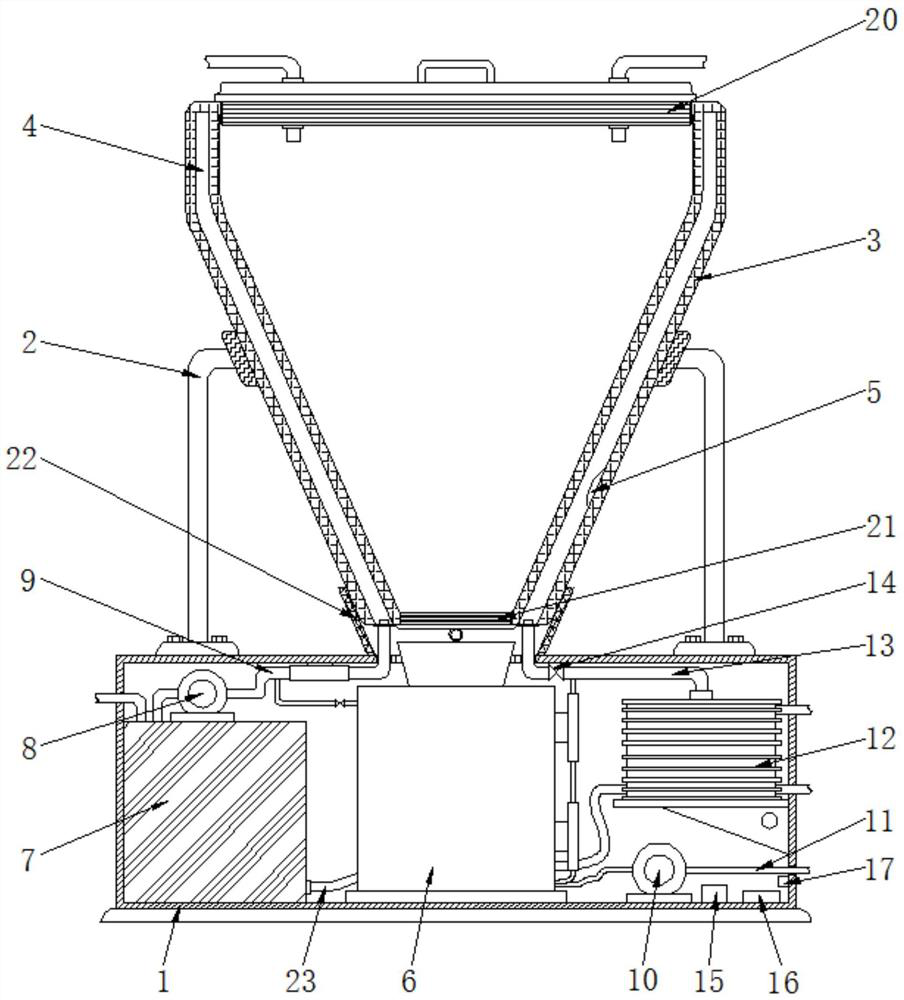
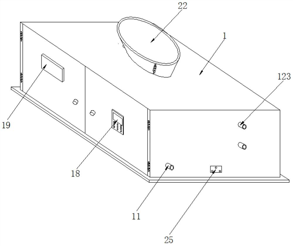
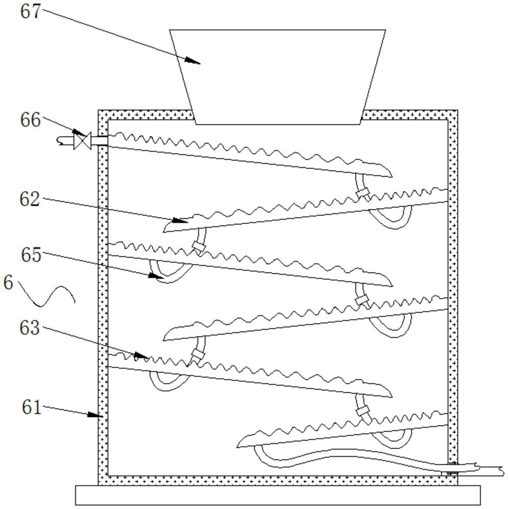
[0034] see Figure 1-6 , the embodiment of the present invention provides a technical solution: an environment-friendly boiler pressure vessel waste heat recovery device, including a chassis 1, the front of the chassis 1 is hinged with a door, and both sides of the top of the chassis 1 are connected by bolts to support Frame 2, and the pressure vessel body 3 is placed in the tapered collar of the support frame 2, the inside of the pressure vessel body 3 is pro...


PUM


Abstract

The invention discloses an environment-friendly waste heat recovery device of a boiler pressure vessel and a working method of the environment-friendly waste heat recovery device. The environment-friendly waste heat recovery device comprises a machine box. A supporting frame is fixedly connected to the two sides of the top of the machine body through bolts, and a pressure vessel body is placed ina conic sleeve ring of the supporting frame. Empty grooves are formed in the pressure vessel body, and a temperature sensor is fixedly mounted on the inner wall of one empty groove. The number of outlets of the empty grooves is two. The invention relates to the technical field of boiler waste heat recovery equipment. According to the environment-friendly waste heat recovery device of the boiler pressure vessel and the working method of the environment-friendly waste heat recovery device, omni-directional waste heat recovery on the boiler pressure vessel can be achieved, the problems that wasteheat recovery is only carried out on boiler waste slag, and waste heat resources on the inner wall of the boiler pressure vessel are still wasted are solved well, the waste heat recovery effect is greatly enhanced, meanwhile, waste heat recovery is carried out on liquid waste, gas waste and solid waste, and the aim of carrying out comprehensive waste heat recovery on the boiler pressure vessel isachieved well.

Description

technical field [0001] The invention relates to the technical field of boiler waste heat recovery equipment, in particular to an environment-friendly boiler pressure vessel waste heat recovery device and a working method thereof. Background technique [0002] Boiler pressure vessel is the full name of boiler and pressure vessel, because they belong to special equipment and occupy a very important position in production and life. In industrial production, equipment with specific process functions and certain pressure is called pressure vessel, storage and transportation vessel , reaction vessels, heat exchange vessels and separation vessels are all pressure vessels. In order to distinguish them from general vessels (atmospheric pressure vessels), only vessels that meet the following three conditions at the same time are called pressure vessels: 1. The highest working pressure ( Pw) is greater than or equal to 0.1Mpa (excluding hydrostatic pressure, the same below); 2. The inn...

Claims


Application Information

Patent Timeline
Patent Type & Authority Patents(China)
IPC IPC(8): F28D20/00F28D21/00F28F21/08F28F27/00
CPCF28D20/0034F28D21/00F28D2021/0024F28F21/085F28F27/00Y02E60/14
Inventor 郭东伟陈林侯永柱王文民刘华锁
Owner 合肥化机装备制造有限公司
Why Eureka
Try Eureka