A system and method for estimating the rotor position and speed of a permanent magnet synchronous motor

A permanent magnet synchronous motor and rotor position technology, applied in the estimation/correction of motor parameters, control systems, electronic commutators, etc., can solve problems such as the phase delay of the low-pass filter of the observer

Active Publication Date: 2021-06-15
HARBIN INST OF TECH
View PDF4 Cites 0 Cited by
  • Summary
  • Abstract
  • Description
  • Claims
  • Application Information

AI Technical Summary

Problems solved by technology

[0003] In order to solve the chattering of the permanent magnet synchronous motor sliding mode position observer and the phase delay caused by the low-pass filter used in the traditional estimation system, the present invention proposes a permanent magnet synchronous motor rotor position and The speed estimation system and method are as follows:

Method used


Image

  • A system and method for estimating the rotor position and speed of a permanent magnet synchronous motor
  • A system and method for estimating the rotor position and speed of a permanent magnet synchronous motor
  • A system and method for estimating the rotor position and speed of a permanent magnet synchronous motor

Examples


Embodiment 1

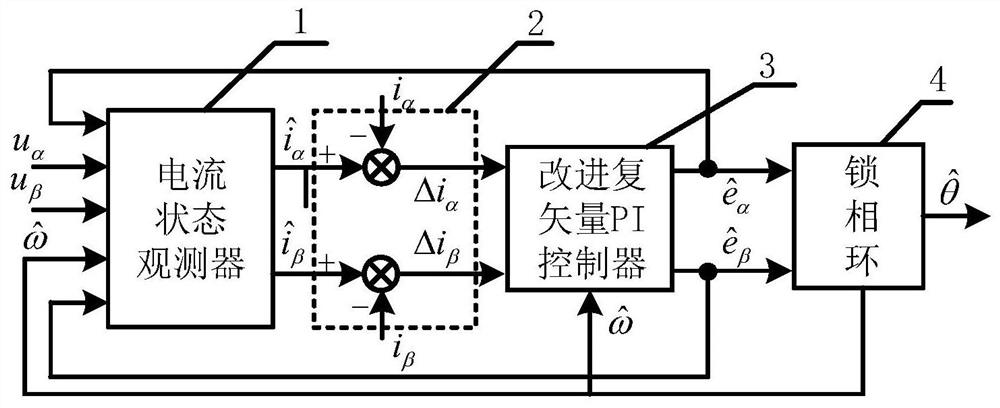
[0041] A permanent magnet synchronous motor rotor position and speed estimation system using an improved sliding mode observer, such as figure 1 As shown, the technical solutions adopted are as follows:

[0042] The system adopts a sliding mode observer, and the sliding mode observer includes a current state observer 1, a comparator 2, an improved complex vector PI controller 3 and a phase-locked loop 4; the signal output terminal of the current state observer 1 Be connected with the signal input end of described comparator 2; The signal output end of described comparator 2 is connected with the signal input end of described improved complex vector PI controller 3; The signal output end of described improved complex vector PI controller 3 It is connected with the signal input end of the phase-locked loop 4; the feedback signal output end of the improved complex vector PI controller 3 is connected with the feedback signal input end of the current state observer 1 . The input o...

Embodiment 2

[0057] A method for estimating the rotor position and speed of a permanent magnet synchronous motor using an improved sliding mode observer, the method for estimating the rotor position and speed of a permanent magnet synchronous motor includes:

[0058] Step 1: The voltages of the α and β axes of the permanent magnet synchronous motor are input into the current state observer, and the current observation values ​​of the α and β axes are obtained through the processing of the current state observer

[0059] Step 2: The current observation values ​​of the α and β axes The input is to the comparator, where the current observations of the α and β axes are combined by and the α and β axis current detection values ​​of the α and β axes i α i β Compare and obtain the α and β axis current deviation Δi α , Δi β ;

[0060] Step 3: The α and β axis current deviation Δi α , Δi β Input into the improved complex vector PI controller; make the current deviation Δi α , Δi β Mult...


PUM


Abstract

The invention provides a permanent magnet synchronous motor rotor position and speed estimation system and method using an improved sliding mode observer, which belongs to the technical field of motor control. The system adopts a sliding mode observer composed of a current state observer, a comparator, an improved complex vector PI controller and a phase-locked loop. The input of the current state observer is the α and β axis voltage, and the estimated value of the α and β axis back EMF After calculating the difference between the observed current value and the detected current value, the estimated back EMF is obtained through the improved complex vector PI controller, and then input to the phase-locked loop to obtain the rotor position and speed. The system and method improve the stability of the observer.

Description

technical field [0001] The invention relates to a permanent magnet synchronous motor rotor position and speed estimation system and method using an improved sliding mode observer, belonging to the technical field of motor control. Background technique [0002] In the occasions with low cost and high requirements on the sensor environment, the position sensorless control technology is widely used. The position estimation methods of permanent magnet synchronous motors are usually divided into two categories: low-speed estimation methods and medium-high speed estimation methods. The observer observes the motor back EMF or flux linkage related to the rotor angle in real time, and extracts the rotor angle and speed information from it. It is a common method for position and speed estimation in the middle and high speed sections. , adaptive observer, extended Kalman filter, etc. Among them, the sliding mode observer has the advantages of simple structure and good robustness, and...

Claims


Application Information

Patent Timeline
Patent Type & Authority Patents(China)
IPC IPC(8): H02P6/17H02P6/182H02P23/14H02P23/00H02P23/12H02P25/022
CPCH02P6/182H02P23/0009H02P23/12H02P23/14H02P25/022H02P2207/05H02P6/17
Inventor 安群涛张建秋安琦刘兴亚李帅谢成龙
Owner HARBIN INST OF TECH
Why Eureka
Try Eureka