Visual constant volume combustion bomb device and method with controllable turbulent flow-flame blast wave effect

A constant-volume incendiary bomb and constant-volume combustion technology, which is applied to measuring devices, internal combustion engine tests, engine tests, etc., can solve the problems of inability to accurately infer the turbulent flow movement in the cylinder and the spontaneous combustion state of the end, and achieve simple structure, low cost effect

Inactive Publication Date: 2020-02-14
TIANJIN UNIV
View PDF7 Cites 8 Cited by
  • Summary
  • Abstract
  • Description
  • Claims
  • Application Information

AI Technical Summary

Problems solved by technology

However, the gasoline engine combustion chamber is cylindrical, and it is impossible to accurately infer the turbulent flow movement in the cylinder and the end spontaneous combustion combustion state by using a spherical combustion chamber

Method used


Image

  • Visual constant volume combustion bomb device and method with controllable turbulent flow-flame blast wave effect
  • Visual constant volume combustion bomb device and method with controllable turbulent flow-flame blast wave effect
  • Visual constant volume combustion bomb device and method with controllable turbulent flow-flame blast wave effect

Examples


Embodiment Construction

[0038] The present invention will be further described below in conjunction with the accompanying drawings and specific embodiments, but the following embodiments in no way limit the present invention.

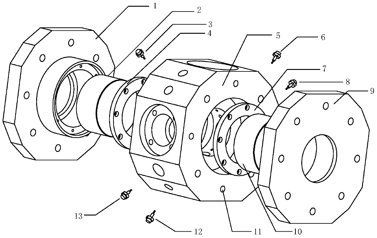
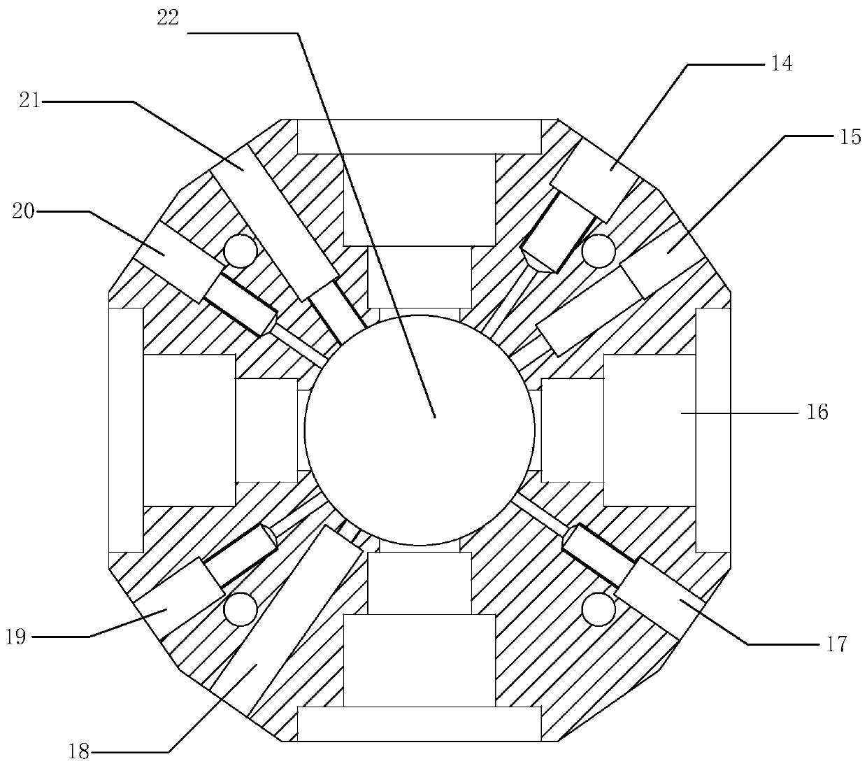
[0039] The present invention proposes a controllable turbulence-flame shock wave action visual constant volume incendiary device, including a constant volume combustion device, a fuel supply system, a heating system, an ignition system, a high-speed photography system, an intake and exhaust system, and pressure acquisition in a cylinder system and synchronous controller.

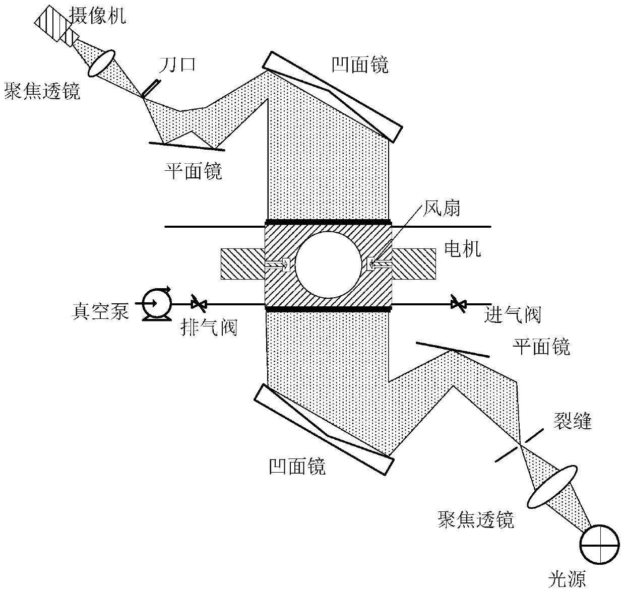
[0040] Such as figure 1 As shown, the constant volume projectile is located at figure 1 In the center, there are vacuum pumps, exhaust valves, and intake valves on the left and right sides respectively. The light is first emitted by the light source, focused by the focusing lens on the lower right, and then passes through the crack to the plane mirror, and then is reflected by the plane mirror to the concav...


PUM

PropertyMeasurementUnit
thicknessaaaaaaaaaa

Abstract

The invention discloses a visual constant volume combustion bomb device with controllable turbulent flow-flame blast wave effect. The device comprises a constant volume combustion device, a fuel supply system, a heating system, an ignition system, a high-speed photography system, an air intake and exhaust system, an in-cylinder pressure acquisition system and a synchronous controller; the constantvolume combustion device comprises a combustion bomb body as well as fans and a driving motor thereof, a combustion chamber is formed in the middle of the combustion bomb body, four fan mounting holes which are uniformly distributed in the circumferential direction, radially arranged and communicated with the combustion chamber are formed in the combustion bomb body, one of the fans is mounted ineach fan mounting hole, the four fans are oppositely arranged, and a replaceable ventilation porous plate is arranged in each fan mounting hole and between an air outlet direction of the corresponding fan and the combustion chamber. In the device disclosed by the invention, multiple replaceable ventilation porous plates with different pore diameters and pore numbers are arranged, turbulent flamesat different intensities can be produced by replacing the ventilation porous plates, and interaction between the turbulent flames at different intensities and blast waves as well as influence on spontaneous combustion of an end gas are studied.

Description

technical field [0001] The invention relates to a combustion system of an internal combustion engine, in particular to a test device for simulating the interaction between turbulent flame and shock wave and the spontaneous combustion of terminal gas. Background technique [0002] In recent years, engines are facing two major problems: the aggravation of the energy crisis and the increasingly stringent emission regulations, which promote the miniaturization of engines with high efficiency and low emissions. Therefore, supercharging technology and increasing the compression ratio have been further applied, and this has led to an increase in the possibility of knocking. Now it is generally believed that knocking is caused by the spontaneous combustion of the end mixture: during the combustion process of a gasoline engine, as the combustion process proceeds and the flame spreads normally, the temperature and pressure of the end gas at the final combustion position continue to in...

Claims


Application Information

Patent Timeline
Patent Type & Authority Applications(China)
IPC IPC(8): G01M15/10G01M15/04G01M15/02G01N21/84
CPCG01M15/02G01M15/048G01M15/10G01N21/84G01N2021/8411
Inventor 卫海桥李匡迪周磊赵健福舒歌群
Owner TIANJIN UNIV
Why Eureka
Try Eureka