
Three-dimensional entity unit modeling method of gear system

A three-dimensional entity and gear system technology, applied in the field of gear system dynamics analysis, can solve the problems of high-order dynamic model equations, difficulty in solving, inconvenient coupling analysis of subsystems, etc., to achieve high-efficiency and accurate analysis methods that guarantee model accuracy , The effect of solving the contradiction between solution efficiency and model accuracy

Active Publication Date: 2020-02-18
XI'AN PETROLEUM UNIVERSITY
View PDF4 Cites 2 Cited by
  • Summary
  • Abstract
  • Description
  • Claims
  • Application Information

AI Technical Summary

Problems solved by technology

The advantage of the transfer matrix method is that the order of the matrix will not increase with the increase of the number of degrees of freedom of the system. The disadvantage is that it is not convenient to perform coupling analysis between subsystems when calculating high-order frequencies or when the rotor system is relatively large.
The three-dimensional finite element method does not perform a large number of simplifications on the structure, the model is accurate, and it is suitable for quantitative analysis
However, the dynamic model equations established by the three-dimensional finite element method are of high order and difficult to solve, and are generally only suitable for static or quasi-static analysis

Method used


Image

  • Three-dimensional entity unit modeling method of gear system
  • Three-dimensional entity unit modeling method of gear system
  • Three-dimensional entity unit modeling method of gear system

Examples


Embodiment example

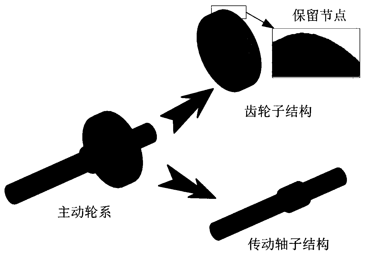
[0087] In order to verify the validity of the established model, the solid model of the drive shaft system of the gear transmission system as shown in the figure is established by using SOLIDWORKS and HYPERMESH, and the finite element mesh is divided. Then use the aforementioned method to build the reduced degree of freedom model of the model. Before the reduced degree of freedom, there are tens of thousands of degrees of freedom, but after the reduction, there are only a few hundred degrees of freedom, so that the solution of the dynamic equation is greatly improved. The following is a comparative analysis of the models from three perspectives: modal, static response, and dynamic response.

[0088] Modal analysis: the finite element model of the drive shaft of the gear transmission system such as Figure 5 (a) shown. Firstly, a fixed constraint is imposed on the node where the bearing is located, and the modal analysis of the model is carried out by using ANSYS to obtain the...


PUM


Abstract

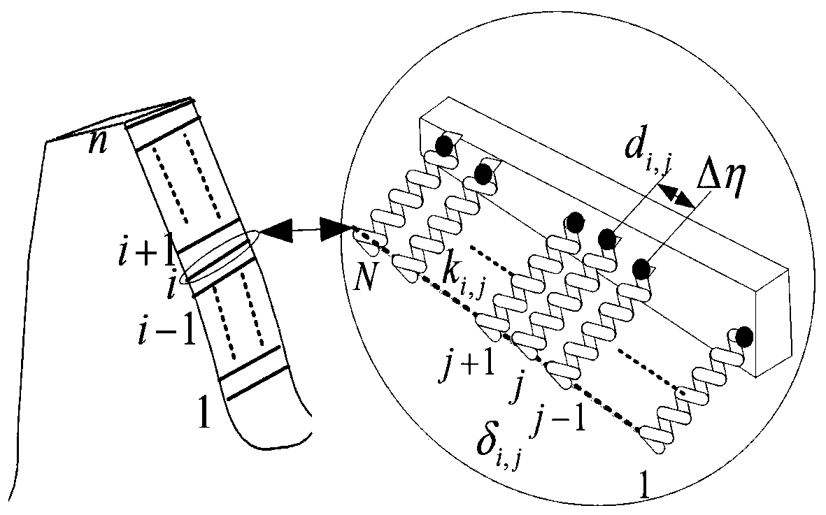
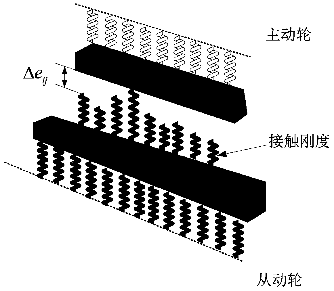
A three-dimensional entity unit modeling method of a gear system comprises the steps that firstly, according to the structural characteristics of the gear transmission system, HYPERMESH software is used for preprocessing a complex structure, three-dimensional entity unit models of a gear substructure and a transmission shaft substructure are established respectively, and accurate division and optimization of grids are carried out; then, ANSYS software is used for carrying out modal analysis and extracting a mass matrix and a rigidity matrix; then, nonlinear factors such as time-varying rigidity are considered, and gear tooth meshing of the gear transmission system is modeled through the Pasternak elastic foundation beam theory; finally, according to the interface displacement coordinationcondition, integrating, coupling and dimensionality reduction are conducted on the models of the transmission shaft, the gear and the bearing system through a modal synthesis method, and a high-precision gear transmission system dynamic model matched with the dynamic characteristics of the equipment is established. According to the method, the model precision can be guaranteed, and the calculationefficiency can be remarkably improved, so that a more efficient and accurate method is provided for quantitative analysis of the vibration of the gear transmission system.

Description

technical field [0001] The invention belongs to the technical field of dynamic analysis of a gear system, and in particular relates to a three-dimensional solid unit modeling method of a gear system. Background technique [0002] Gear transmission, because of its compact structure, stable transmission ratio and high transmission efficiency, is widely used in various industrial machinery and equipment, and plays an irreplaceable role. As a key component for transmitting power and energy, the vibration characteristics of the gear system directly affect the working accuracy, noise and working reliability of the entire mechanical system. Therefore, the dynamic analysis of the gear system is the key to understand whether the design of the dynamic characteristics of the system is reasonable or not. The gear transmission system is a complex dynamic system, and the establishment of the dynamic model of the gear transmission system is the central task of the gear dynamics analysis. ...

Claims


Application Information

Patent Timeline
IPC IPC(8): G06F30/23G06F30/17G06T17/00G06F119/14
CPCG06T17/00Y02T90/00
Inventor 万志国李昊关元孟琪窦益华
Owner XI'AN PETROLEUM UNIVERSITY
Learn More