Rapid bleeding arresting device for field first aid and use method
An on-site, hemostatic clip technology, applied in the fields of application, medical science, surgery, etc., can solve the problems of difficult to complete independently, short treatment time for the wounded, and few medical personnel, and achieve the effect of convenient use, improved treatment effect, and convenient hemostasis.
- Summary
- Abstract
- Description
- Claims
- Application Information
AI Technical Summary
Problems solved by technology
Method used
Image
Examples
Embodiment 1
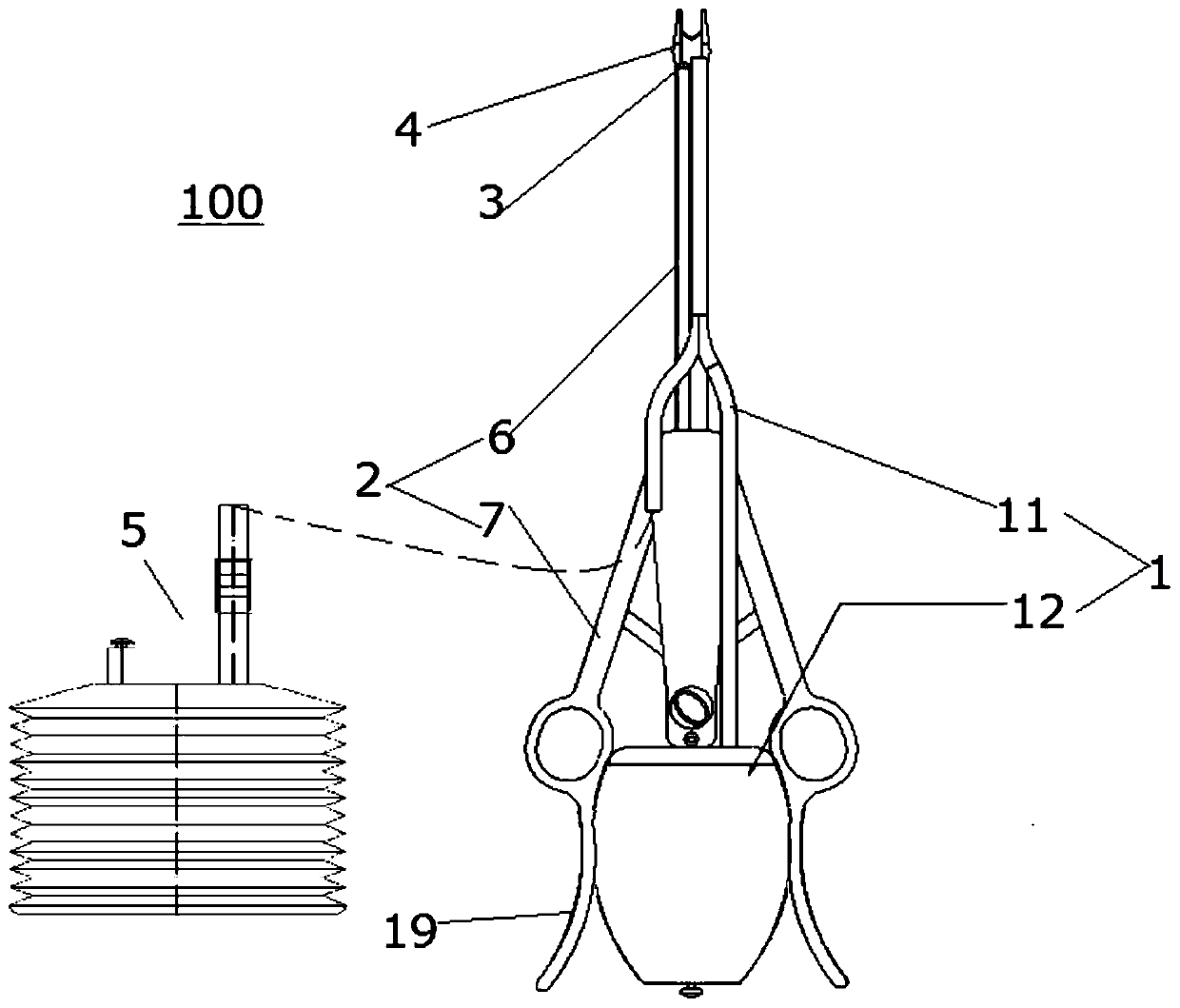
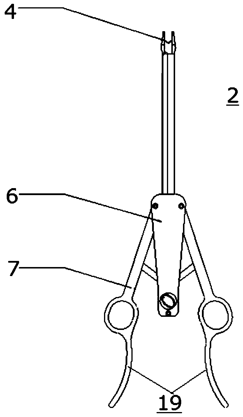
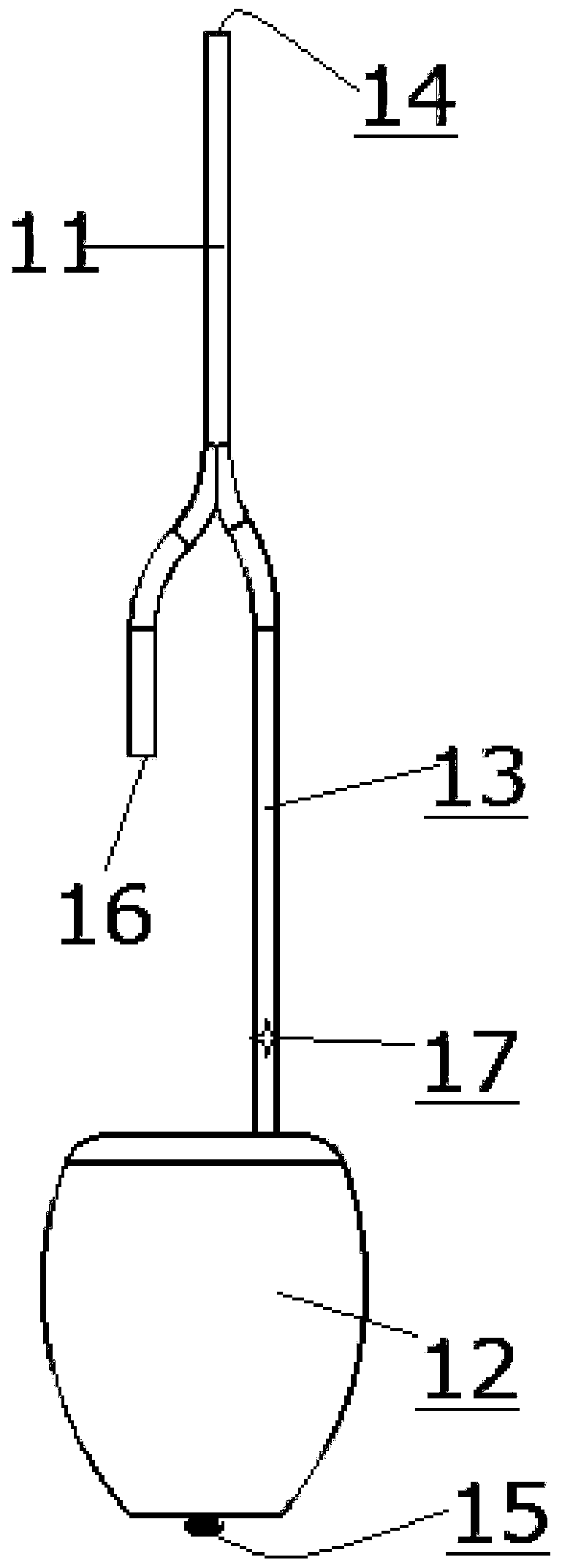
[0050] Such as figure 1 As shown, the on-site emergency hemostasis device 100 of the present invention includes a clamp 2 and a conjoined manual suction device 1 connected (for example nested) on the clamp 2 .
[0051] The clamp 2 comprises a handle 7 and a body 6 . Such as figure 1 , 2 As shown, a hemostatic clip can be installed at the far end of the body 6, such as a titanium clip 4, which can be single-shot or multiple, preferably 2-6 pieces, preferably 6-10 pieces, or preferably more than 10 pieces, that is, Constitute the so-called disposable burst titanium clamp. The clamp is also provided with a safety switch. When the safety switch is locked, at least one pliers handle 7 can still be opened and closed manually, so that the space between the two pliers handles 7 increases and decreases accordingly.
[0052] Inside or outside the body 6 is provided an illuminating lamp 3 for providing illumination, such as an LED lamp, whose power source comes from a replaceable bat...
Embodiment 2
[0066] This embodiment is a modified example of the first embodiment, and the same symbols are used for the parts common to the first embodiment, and their descriptions are omitted. The difference is mainly in the suction and discharge path of accumulated blood, so in the following Figure 4 In the schematic diagram, omit to show figure 1 Clamp 2 and light 3 in.
[0067] A one-way valve, an anti-overflow valve, an anti-overflow diaphragm, etc. may be provided on the connecting pipe portion at the far end of the manual pump 12' to prevent blood from flowing into the manual pump 12'. Through the lateral extrusion and stretching of the manual pump 12' by the two clamp handles 7, a negative pressure is formed in the collection part 18 and the suction tube 11, so that the accumulated blood is directly discharged to the collection part 18. In addition, the collection part 18 may also be connected with a split negative pressure suction bottle 5 .
[0068] In this way, the above-me...
Embodiment 3
[0070] In the first embodiment above figure 1 , 2 Among them, the handle actuating parts 19 move away from each other in the transverse direction as they go longitudinally toward the tail of the handle 7, or approach each other and then move away (corresponding to the opposite concave shape). As a result, between the two handle actuating parts 19 there is formed a point of action for the projection of the container 12 , which is especially suitable for the case where the container 12 is formed by a balloon or the like.
[0071] different from this, Figure 5 is a schematic view showing a clamp in another embodiment of the present invention. its with figure 1 , 2 The main difference is that the configuration of the handle actuating portion 19 is substantially opposite.
[0072] In consideration of the situation when the container 12 is made of bellows or the like, it may also be as Figure 5 As shown, the handle actuating parts 19 are formed to approach each other in the ...
PUM
 Abstract
Description
Claims
Application Information
 - R&D
- Intellectual Property
- Life Sciences
- Materials
- Tech Scout
- Unparalleled Data Quality
- Higher Quality Content
- 60% Fewer Hallucinations
Browse by: Latest US Patents, China's latest patents, Technical Efficacy Thesaurus, Application Domain, Technology Topic, Popular Technical Reports.
© 2025 PatSnap. All rights reserved.Legal|Privacy policy|Modern Slavery Act Transparency Statement|Sitemap|About US| Contact US: help@patsnap.com


