Friction wear device

A technology for friction and wear and generating devices, applied in measuring devices, testing wear resistance, instruments, etc., can solve problems such as failure to reach the target order of magnitude, failure to achieve fretting displacement, and difficulty in controlling positive pressure, achieving low cost , improve accuracy, eliminate the effect of force imbalance

Pending Publication Date: 2020-02-21
ZHEJIANG UNIV OF TECH
View PDF0 Cites 1 Cited by
  • Summary
  • Abstract
  • Description
  • Claims
  • Application Information

AI Technical Summary

Problems solved by technology

At present, most of the common fretting friction and wear devices on the market cannot achieve the expected fretting displacement, the target order of magnitude, and it is difficult to control the applied normal pressure, and cannot maintain the positive force on the sample during the experiment. The pressure is uniform, because if the pressure applied to the sample cannot be guaranteed to be uniform, it will cause stress concentration, making the result error larger

Method used


Image

  • Friction wear device
  • Friction wear device
  • Friction wear device

Examples


Embodiment Construction

[0029] The present invention is further described below in conjunction with specific embodiment, but protection scope of the present invention is not limited thereto:

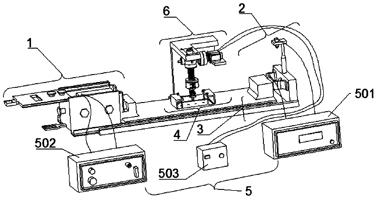
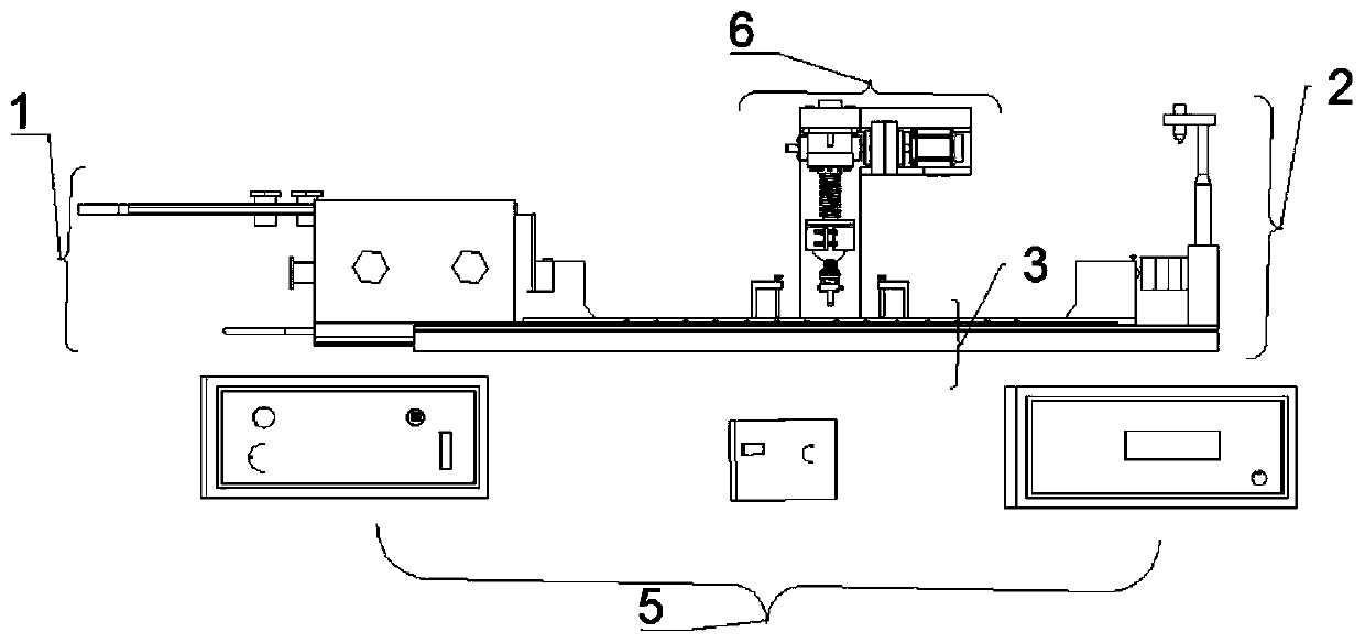
[0030] Referring to the accompanying drawings, a high-precision micro-motion displacement generation device includes a micro-motion displacement generation device 1, a laser distance measurement and resultant force measurement device 2, a displacement transmission device 3, a sample clamp device 4, a control and data acquisition device 5 and a positive pressure Applicator 6;

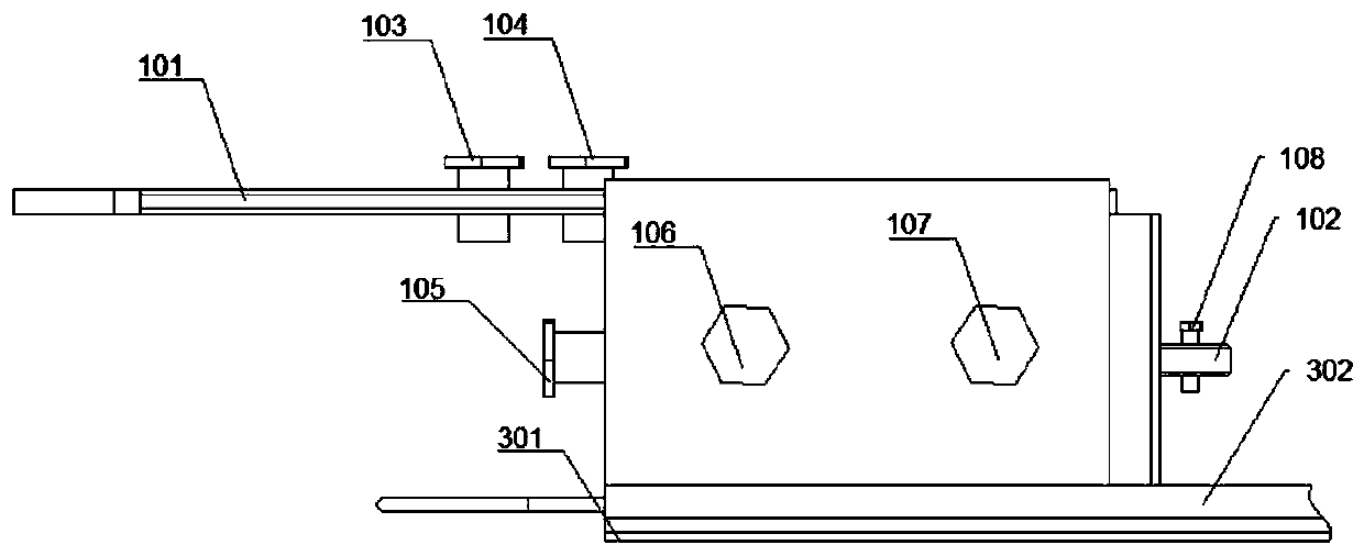
[0031] Described displacement conduction device comprises: the first support plate 301 of three parallel arrangements, the second support plate 302 and the 3rd support plate 303, the length of the first support plate 301 is greater than the length of the second support plate 302, the second support plate The length of 302 is greater than the length of the third support plate 303; the first support plate 301 is horizontally arranged on the...


PUM


Abstract

A friction wear device comprises a micro displacement generation device, a laser ranging and resultant force measurement device, a displacement conduction device, a sample clamp device, a control anddata acquisition device and a positive pressure applying device; the displacement conduction device comprises a first supporting plate, a second supporting plate and a third supporting plate which arearranged in parallel, wherein the second supporting plate is slidably embedded in the first supporting plate, and the third supporting plate is slidably embedded in the second supporting plate; a first push block and a second push block are oppositely arranged at two ends of the third support plate; a micro displacement generating device and a laser ranging and resultant force measuring device are oppositely arranged at two ends of the second support plate; the left end of the first push block is fixedly connected with the micro-motion displacement generation device, and the right end of thesecond push block abuts against the laser ranging and resultant force measurement device. A sample groove is formed in the middle of the third supporting plate, and a positive pressure applying deviceis arranged above the sample groove. The friction coefficient of the material surface can be measured in real time when a fretting friction test is carried out.

Description

technical field [0001] The invention relates to the field of fretting friction and wear experimental devices, in particular to a friction and wear device. Background technique [0002] The damage caused by fretting wear has always been the focus of attention in military devices, aerospace, automobiles and other fields. Fretting wear refers to the relatively small relative movement of two components on the contact surface. Fretting wear causes friction and wear on the contact surface, which leads to loosening of the components and loss of efficiency, especially in some high-speed, corrosion and other environments. Under the condition of relatively harsh factors, this hazard is even greater. For example, the most likely form of wear for aircraft connectors is fretting wear. During the working process of the connection between the rotor blade and the disc of the aeroengine, the temperature stress is generated due to the vibration of the engine or the temperature cycle between ...

Claims


Application Information

Patent Timeline
Patent Type & Authority Applications(China)
IPC IPC(8): G01N3/56G01N3/04
CPCG01N3/04G01N3/56
Inventor 熊缨何留永朱涛沈永水杨杰余意
Owner ZHEJIANG UNIV OF TECH
Why Eureka
Try Eureka