Fluid-driven tunneling device

A fluid-driven and fluid-dynamic technology, applied in mining equipment, earth-moving, tunneling, etc., can solve the problems of difficulty in meeting endurance, cumbersome maintenance and use, complicated motor structure, etc., and achieves good driving effect, simple structure and large torque. Effect

Pending Publication Date: 2020-02-25
TRANF TECH XIAMEN CO LTD
View PDF0 Cites 1 Cited by
  • Summary
  • Abstract
  • Description
  • Claims
  • Application Information

AI Technical Summary

Problems solved by technology

At present, most gas engine design prototypes are based on piston engines or vane pumps, and the energy conversion is realized through the heat of the heat exchanger to achieve power output, but the structure is complex and the efficiency is low, and it is difficult to meet the requirements of endurance.
[0005] The hydraulic engine is mostly a low-speed hydraulic motor with low working efficiency, and the structure of the motor itself is complicated, the maintenance and use are cumbersome, and the working stability is poor.

Method used


Image

  • Fluid-driven tunneling device
  • Fluid-driven tunneling device
  • Fluid-driven tunneling device

Examples


Embodiment 1

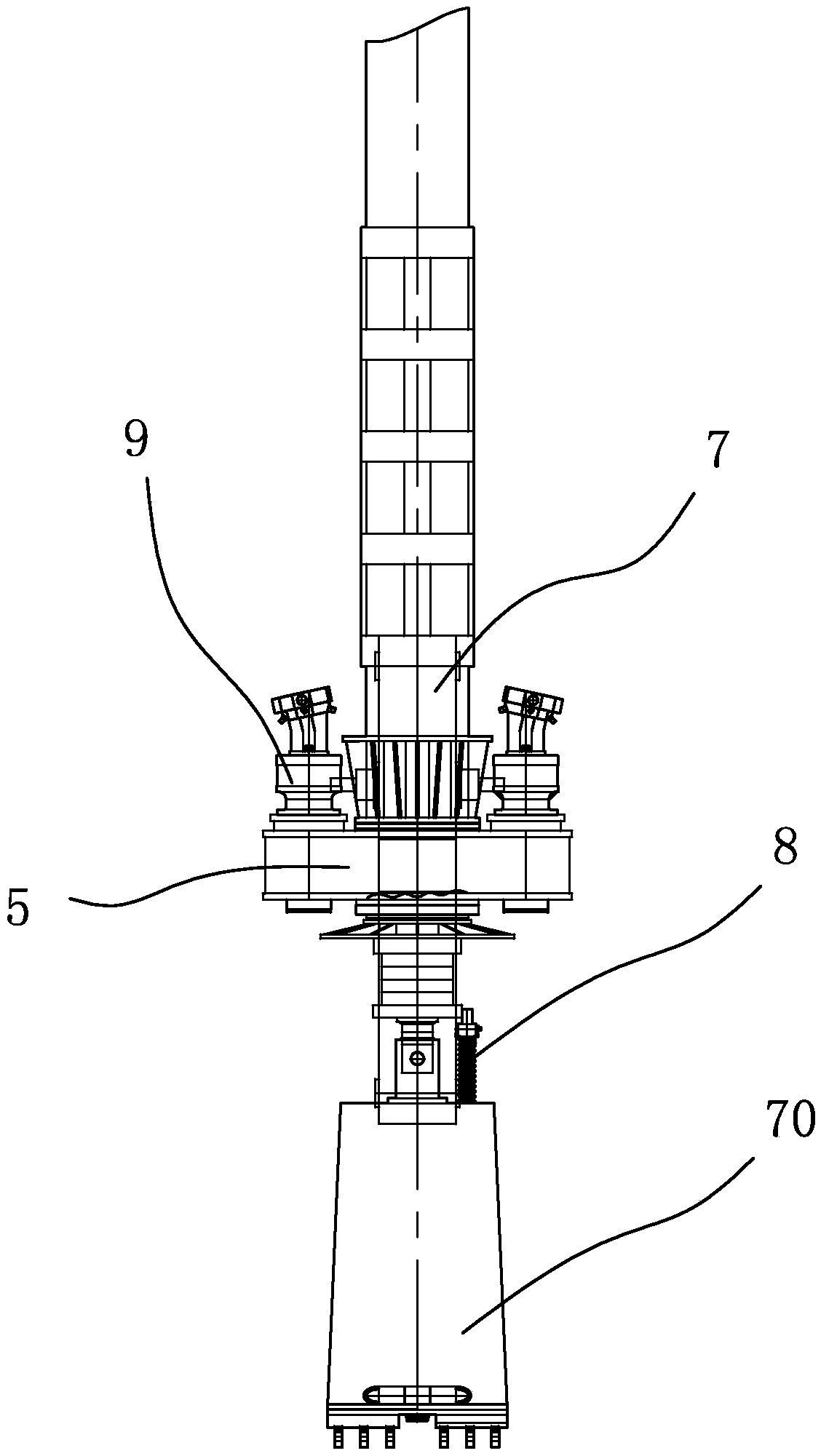
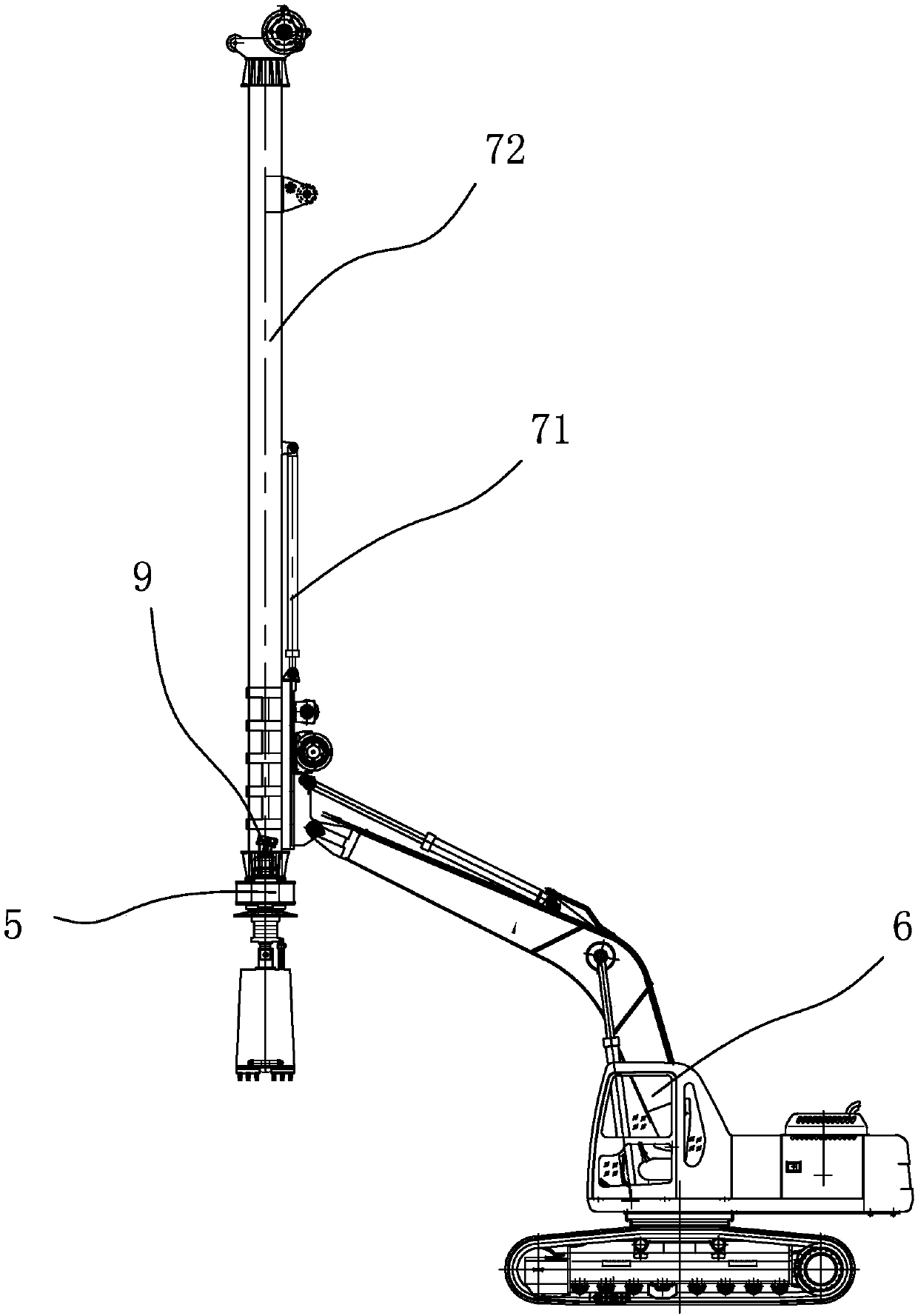
[0051] combine figure 1 with figure 2 As shown, this embodiment provides a fluid-driven tunneling device, which includes a mounting base 5, which has a through hole, and a rotating device 7 is rotatably arranged in the through hole, and two fluid The power device 9 is arranged on the installation base 5 and is respectively connected to the rotation device 7 by transmission.

[0052] The front end of the rotating device is provided with an operating device 8. In this embodiment, the operating device 8 is a drill bit for drilling and excavating the ore rock. The installation base 5 is arranged on the lifting arm of a crawler-type mobile device 6, and the inclination angle can be adjusted. The lifting arm also has a pull-down oil cylinder 71, and the pull-down oil cylinder 71 acts on the upper end 72 of the rotating device 7. , to be used for pressing down the operating device 8.

[0053] see Figure 3 to Figure 6, the fluid power device of this embodiment, it comprises an o...

Embodiment 2

[0073] The fluid-driven tunneling device of this embodiment is basically the same as Embodiment 1, and its main difference is:

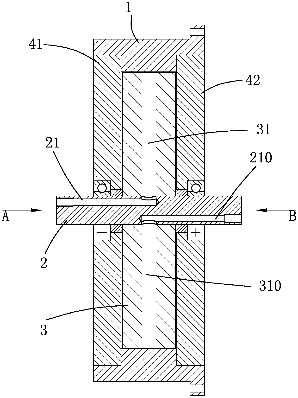
[0074] see Figure 8 to Figure 11 , the fluid power device includes 2 independent work units to form a secondary drive structure, that is, the core body 3 is provided with 2 fluid passages along the circumferential direction, and each fluid passage includes an inlet flow passage 31 and a secondary flushing flow passage 300 of more than one stage and The drainage channel is arranged along the circumferential direction of the core body 3 . The fluid power device includes an outer ring 1, a plurality of driving recesses 11 are arranged on the inner ring surface of the outer ring; a core body 3 is coaxially arranged in the outer ring 1 and can rotate relative to the outer ring, and the outer ring surface of the core body is provided with 2 groups of spouts, discharge ports, and at least one flushing channel between each group of spouts and discharge por...

Embodiment 3

[0077] This embodiment is basically the same as Embodiment 1, and the main difference is that the fluid power device of the present invention includes 4 or more independent working units to form a multi-stage drive structure, and 3 or more fluid lines are arranged on the core along the circumferential direction. Channels, each fluid channel includes an inlet channel and a secondary flushing channel of more than one stage, and is arranged along the circumference of the core body and a drainage channel, and the inlet channel and the drainage channel are arranged on the mating surfaces of the left and right cores. The shaft is provided with the number of inlet shafts and outlet shafts corresponding to the number of fluid channels. The compressed fluid enters from the inlet shaft of the shaft, and is ejected through the core body inlet channel to act on the driving recess of the outer ring to drive the outer ring to rotate. Do work to realize the continuous output of power, and fin...


PUM


Abstract

The invention discloses a fluid-driven tunneling device, which uses fluid such as hydraulic oil, water or compressed air as energy to drive a rotating device to move. With a simple structure, large torque, high rotating speed, high transmission efficiency, low energy consumption and small vibration, the device can meet the requirements of the tunneling device on torque, rotating speed and runningstability well, at the same time, the fluid power device comprises an outer ring and a core body, wherein at least one-step or more-step secondary flushing channels are arranged between a nozzle and an exhaust port of the outer ring surface of the core body, the fluid enters from an inlet channel, is ejected step by step through the nozzle of the core body and the secondary flushing channels, actson at least two driving concave parts in the circumferential direction of the outer ring, generates thrust on the driving concave parts to push the outer ring to rotate and do work, and realizes power output; and finally, the fluid is discharged through the exhaust port of the core body from an exhaust channel.

Description

technical field [0001] The invention discloses a fluid-driven tunneling device, which belongs to the technical field of mining mechanical devices according to the International Patent Classification (IPC). Background technique [0002] Existing various tunneling devices, especially percussion drilling devices, are widely used in building construction and mine operations. It mostly adopts an engine and a rotating device, and the rotating device is driven by the engine to rotate to drive the working device at the front end of the rotating device to work. [0003] Since the operating device needs a large torque when it is working, and the working space is limited, the volume of the engine cannot be too large, and the existing engines are mostly pneumatic engines or hydraulic engines. [0004] For the pneumatic engine in the engine, the current research direction is to develop compact, efficient and reliable small engines, most of which are in the stage of trial and trial produ...

Claims


Application Information

Patent Timeline
Patent Type & Authority Applications(China)
IPC IPC(8): E21D9/10
CPCE21D9/1086
Inventor 许水电李延福许涛
Owner TRANF TECH XIAMEN CO LTD
Why Eureka
Try Eureka