Array fiber laser

A technology of arrayed optical fibers and lasers, applied in the direction of laser devices, etc., can solve the problems of large system volume, low integration, stress damage, etc., and achieve the effects of reducing volume and weight, increasing integration, and improving stability

Pending Publication Date: 2020-02-25
NAT UNIV OF DEFENSE TECH
View PDF0 Cites 0 Cited by
  • Summary
  • Abstract
  • Description
  • Claims
  • Application Information

AI Technical Summary

Problems solved by technology

In these two applications, since each fiber laser is an independent module, the integration level is not high, and there are problems such as large system volume, heavy weight, and high cost; for the second type of multi-mode beam combining, the laser output is also required The optical fiber needs to be spliced ​​with different modules, and there is a risk of stress damage

Method used


Image

  • Array fiber laser
  • Array fiber laser
  • Array fiber laser

Examples


Embodiment Construction

[0031] The specific implementation manners of the present invention will be described in detail below in conjunction with the drawings and embodiments.

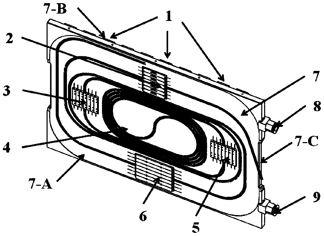
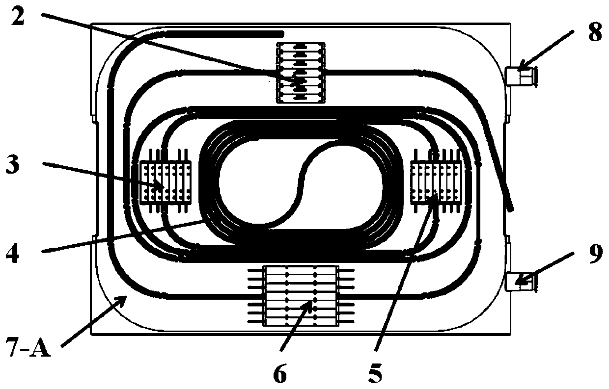
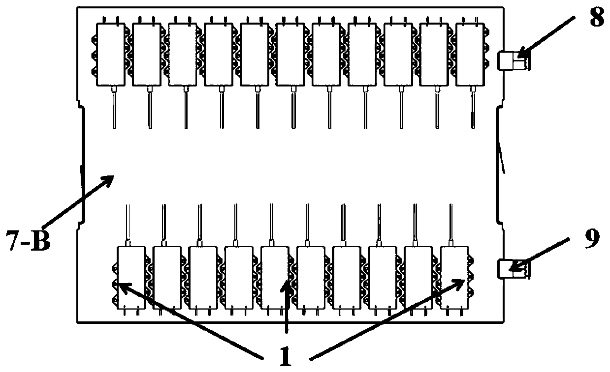
[0032] This embodiment provides an array fiber laser, whose structure refers to figure 1 , 2 And 3, the array fiber laser includes an array fiber laser including a fiber-coupled semiconductor laser array 1, a pump beam combiner array 2, a high-reflection fiber grating array 3, and a gain fiber array 4 that are fixed on the fiber optic device panel 7 and connected in sequence. A low-reflection fiber grating array 5 and a cladding optical filter array 6 . The pump beam combiner array 2, the high reflection fiber grating array 3, the gain fiber array 4, the low reflection fiber Bragg grating array 5 and the cladding optical filter array 6 of the present embodiment correspond to the respective pump beam combiners, high reflection The number of fiber gratings, gain fibers, low-reflection fiber gratings and cladding light filters...


PUM

PropertyMeasurementUnit
diameteraaaaaaaaaa
reflectanceaaaaaaaaaa

Abstract

The invention discloses an array fiber laser. The array fiber laser comprises an optical fiber coupling semiconductor laser array, a pumping beam combiner array, a high-reflection fiber bragggrating array, a gain fiber array, a low-reflection fiber bragggrating array and a cladding light filter array which are connected in sequence; the high-reflection fiber bragg grating array, the gain fiber array, the low-reflection fiber bragg grating array and the cladding light filter array are all fixed to the front face of an optical fiber device panel; gain optical fibers in the gain optical fiber array are distributed in an S shape and are fixed through optical fiber grooves; The optical fiber grooves are formed in the front surface of the optical fiber device panel; the high-reflection fiber bragg grating array and the low-reflection fiber bragg grating array are distributed on the left side and the right side of the gain fiber array; the optical fiber coupling semiconductor laser array is fixed on the back surface of the optical fiber device panel; and the pumping beam combiner array is fixed on the front surface or the back surface of the optical fiber device panel. Under the conditionof improving the integration degree of the laser, the stability of the array fiber laser is ensured, and the array fiber laser is small in size and light in weight.

Description

technical field [0001] The invention belongs to the technical field of fiber lasers, and relates to a column fiber laser. Background technique [0002] In the fields of industrial processing and scientific research, both single-mode fiber laser and multi-mode fiber laser are widely used. One application is the simultaneous use of multiple single-mode, medium-power fiber lasers, and the other is the use of a single high-power multimode fiber laser. For example, in the field of scientific research, it is necessary to use multiple low- and medium-power short-wavelength fiber lasers to pump the wavelength fiber laser to obtain higher power laser output; in the industrial field, it is necessary to combine multiple low- and medium-power fiber lasers into One bundle, used in fields such as metal welding cladding. In these applications, a common requirement is the need for low-to-medium power fiber lasers with multiple outputs. For the first type of application, it is generally n...

Claims


Application Information

Patent Timeline
Patent Type & Authority Applications(China)
IPC IPC(8): H01S3/23
CPCH01S3/23
Inventor 王小林张汉伟杨保来史尘奚小明韩凯王泽锋周朴许晓军司磊陈金宝
Owner NAT UNIV OF DEFENSE TECH
Why Eureka
Try Eureka