Welding equipment for copper processing

A welding equipment and platform technology, applied in welding equipment, auxiliary welding equipment, metal processing equipment, etc., can solve the problems of low production efficiency and insufficient continuity, and achieve the effect of improving production efficiency, wide application range, and realizing continuous welding

Active Publication Date: 2020-02-28
苏州铜盟电气有限公司
View PDF5 Cites 5 Cited by
  • Summary
  • Abstract
  • Description
  • Claims
  • Application Information

AI Technical Summary

Problems solved by technology

[0003] At present, the clamping plate added to the welding equipment for copper processing on the market can fix the copper body, but in the prior art, the continuity during the welding process is insufficient, and the welding machine needs to be suspended until the workpiece is taken out and clamped. The next welding can be performed again, and the production efficiency is low. Therefore, it is necessary to improve the existing welding equipment for copper processing

Method used


Image

  • Welding equipment for copper processing
  • Welding equipment for copper processing
  • Welding equipment for copper processing

Examples


Embodiment 1

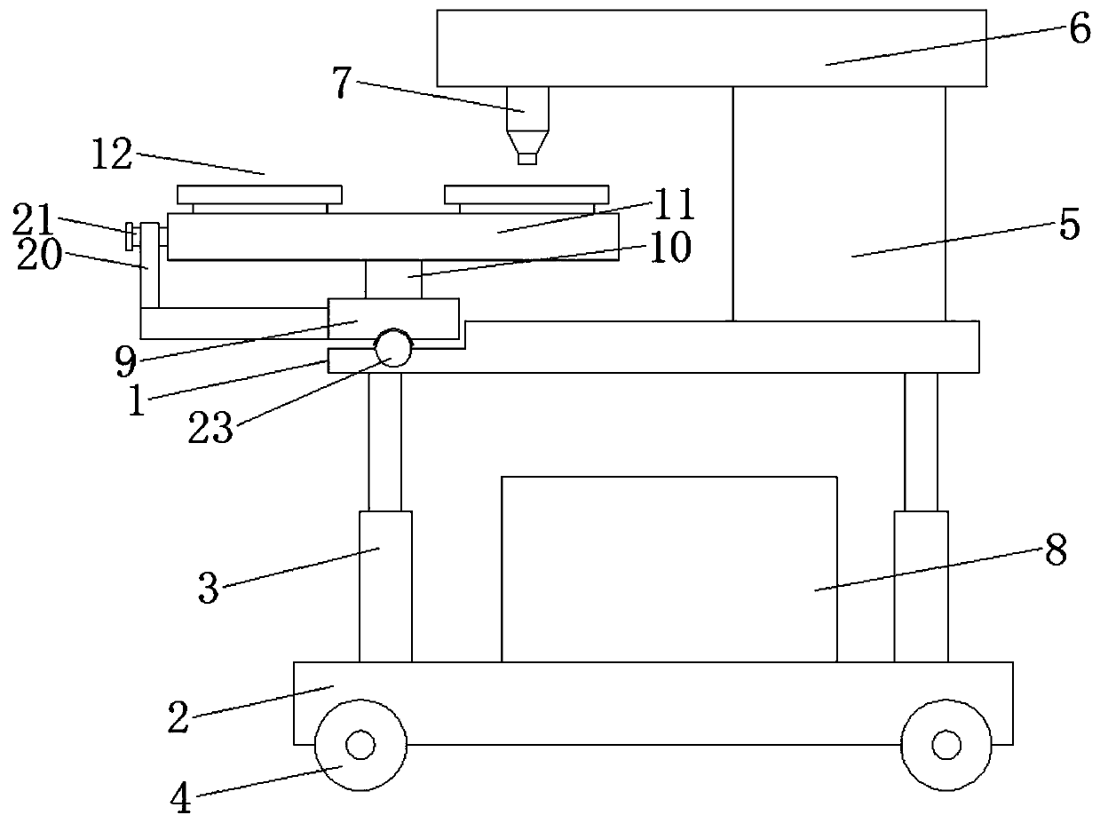
[0019] Please refer to the figure, in the embodiment of the present invention, a welding equipment for copper processing includes a platform 1, a base 2, a lifting leg 3, a roller 4, a support seat 5, a beam 6, an electric welding nozzle 7 and a control box 8; The platform 1 is located above the base 2, and is connected between the platform 1 and the base 2 through a plurality of vertical lifting legs 3. The lifting legs 3 are mainly composed of lifting cylinders, and the height of the platform 1 is driven by the lifting legs 3. , which is convenient for different operators to use; the underside of the base 2 is equipped with rollers 4, which makes the equipment move conveniently; On the beam 6 directly above the platform 1, a downward electric welding nozzle 7 for brazing is installed on the end of the beam 6 to perform welding operations on the workpiece below, and the control box 8 is fixed on the base 2 to control the startup and shutdown of the equipment components .

[...

Embodiment 2

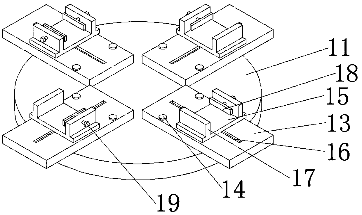
[0023] In Embodiment 1, the chute 16 can also be arranged in a direction perpendicular to the radial direction of the rotating disk 11, so that the moving seat 15 on it can move in another direction to realize welding in different directions, It is also possible to adjust the direction of the chute 16 as required, so that the electric welding nozzle 7 is convenient for welding the workpiece when the moving seat 15 is moved, so as to improve the flexibility of use.

[0024] When in use, the height of the platform 1 is adjusted through the lifting legs 3, which is convenient for operation. The clamping and moving mechanism 12 is selected according to the workpiece to be welded, and the workpiece is installed on the clamping and moving mechanism 12. By rotating the rotating disk 11, different clamping Hold the moving mechanism 12 directly below the electric welding nozzle 7, start the electric welding nozzle 7 to weld the bottom, and at the same time push the moving seat 15 to mov...


PUM


Abstract

The invention relates to the field of copper processing and specifically discloses welding equipment for copper processing. The welding equipment for copper processing comprises a platform, a base, lifting supporting legs, rolling wheels, a supporting base, a cross beam, an electric welding spray head and a control cabinet. An adjusting seat swinging around the midpoint is arranged at the left endof the platform. A rotary shaft perpendicular to the surface of the adjusting seat is rotatably connected to the upper surface of the adjusting seat. A rotary disk parallel to the adjustment seat iscoaxially fixed to the upper end of the rotary shaft. A plurality of detachable clamping and moving mechanisms are mounted on the upper surface of the rotary disk. Each clamping and moving mechanism comprises a mounting plate, fixing bolts, a movable seat and a sliding groove. The inclination angle of the electric welding spray head can be changed through the adjusting seat capable of swinging. The welding equipment for copper processing can conduct welding on different positions, especially weld seams in the vertical direction, can conduct continuous welding on workpieces mounted on the clamping and moving mechanisms, has no influence on the welding process during discharging and feeding and can save time and improve the production efficiency.

Description

technical field [0001] The invention relates to the field of copper processing, in particular to a welding device for copper processing. Background technique [0002] Copper is a transitional element. Pure copper is a soft metal. The surface is red-orange with metallic luster when it is just cut, and the single substance is purple. Good ductility, high thermal conductivity and electrical conductivity, so it is the most commonly used material in cables and electrical and electronic components. It can also be used as a building material and can form many kinds of alloys. Copper alloys have excellent mechanical properties and low electrical resistivity, the most important of which are bronze and brass. In addition, copper is also a durable metal that can be recycled many times without compromising its mechanical properties. Soldering equipment is required for copper processing. [0003] At present, the clamping plate added to the welding equipment for copper processing on the...

Claims


Application Information

Patent Timeline
Patent Type & Authority Applications(China)
IPC IPC(8): B23K37/00B23K37/04
CPCB23K37/00B23K37/0443B23K37/0452
Inventor 刘强
Owner 苏州铜盟电气有限公司
Why Eureka
Try Eureka