Double-station synthetic aperture radar imaging method based on time reversal

A technology of synthetic aperture radar and imaging method, which is applied in the direction of radio wave reflection/re-radiation, instruments, measuring devices, etc., and can solve the problem of increased difficulty and complexity of imaging processing algorithms, increased detection complexity and hardware costs, and imaging effects Influence and other issues, to achieve strong maneuverability and concealment, flexible measurement, and improve the effect of distance resolution

Active Publication Date: 2020-02-28
NANJING UNIV OF SCI & TECH
View PDF4 Cites 3 Cited by
  • Summary
  • Abstract
  • Description
  • Claims
  • Application Information

AI Technical Summary

Problems solved by technology

[0004] The existing bistatic SAR imaging algorithm mainly adopts the CS algorithm, which performs matching filtering on the echo signal in the distance dimension and the direction dimension, so as to obtain high resolution, but the main defect is: due to the error of the bistatic platform Existence, the difficulty and complexity of the imaging processing algorithm are significantly increased, this is because the error of the bistatic SAR is caused by the transceiver platform, and the influencing factors may be different
However, this type of method requires multiple antenna elements to perform multiple sending and receiving detections to obtain echo signals to construct an airspace transmission matrix, which increases the complexity of detection and hardware costs, and the imaging effect is affected in the ultra-wideband system.

Method used


Image

  • Double-station synthetic aperture radar imaging method based on time reversal
  • Double-station synthetic aperture radar imaging method based on time reversal
  • Double-station synthetic aperture radar imaging method based on time reversal

Examples


Embodiment

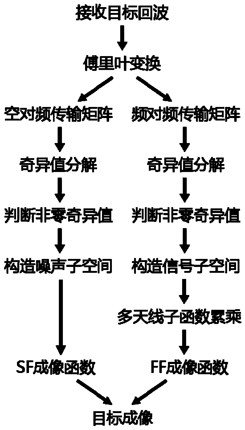
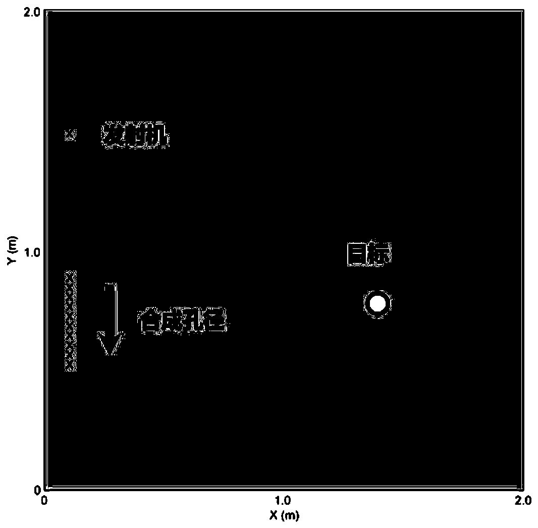
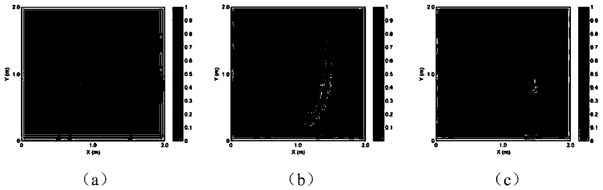
[0075] In this embodiment, the finite difference time domain (FDTD) method is used to model the antenna and target detection scene, to simulate echo data and to perform data simulation on the imaging method proposed by the present invention. The bistatic SAR mode used in the simulation is that the transmitter is fixed, the receiver moves and the receiver moves towards the y-axis to form a synthetic aperture. The scene settings are as follows figure 2 As shown, the simulation results are as image 3 shown. Depend on image 3 (a), image 3 (b) It can be seen that the imaging results of the SF imaging function and the FF imaging function have higher tangential resolution and higher radial resolution respectively, and the combination of the two functions can obtain higher Resolution imaging results (such as image 3 (c) shown).

[0076] This example builds the following actual experimental system:

[0077] (1) Adopt PulsOn 440 (P440) ultra-wideband wireless transceiver modu...


PUM


Abstract

The invention discloses a double-station synthetic aperture radar imaging method based on time reversal. The method comprises the following steps: constructing a double-station synthetic aperture radar system by utilizing an ultra-wideband wireless transceiver module and a stepping motor module; according to the target scattering signal, constructing a frequency domain transmission matrix: SF-MDMand FF-MDM; respectively carrying out singular value decomposition on the two matrixes, and dividing a linear space taking a left singular vector as a substrate into a signal subspace and a noise subspace; constructing SF and FF imaging functions by utilizing the two subspaces; multiplying the two functions to obtain a new imaging function, and realizing high-resolution imaging in each direction by utilizing the imaging function. According to the invention, a double-station SAR array mode in which a transmitter and a fixed receiver move is adopted, the maneuverability and the concealment are stronger, and the measurement is flexible; target detection is carried out by using an ultra-wideband signal, so the robustness is high; by combining time reversal, a new high-resolution time reversalalgorithm is provided, an imaging result with higher resolution can be obtained, an antenna array is not needed for multiple times of transceiving measurement, and the application range is wide.

Description

technical field [0001] The invention relates to the field of radar signal processing, in particular to a time-reversal-based bistatic synthetic aperture radar imaging method. Background technique [0002] Synthetic Aperture Radar (SAR) is a high-resolution microwave imaging system. Traditional SAR is based on the principle of synthetic aperture and uses pulse compression technology to obtain high-resolution remote sensing images in the range and azimuth directions. It has the characteristics of all-day and all-weather. It has played a huge role in national defense construction and economic construction. In terms of military reconnaissance, the application of SAR is of great value in understanding battlefield conditions and obtaining enemy intelligence; in terms of microwave remote sensing, SAR has begun to be used in civilian fields such as geological surveys, engineering geology, and marine research. [0003] According to the spatial position relationship of the sending an...

Claims


Application Information

Patent Timeline
Patent Type & Authority Applications(China)
IPC IPC(8): G01S13/90G01S7/295G01S7/40G01S7/41
CPCG01S13/9011G01S7/295G01S7/4052G01S7/41G01S13/9058G01S13/9017
Inventor 关睿林张祺婧池灵雅
Owner NANJING UNIV OF SCI & TECH
Why Eureka
Try Eureka