Generating tool power head structure

A technology of power head and knife expansion, applied in the directions of large fixed members, maintenance and safety accessories, feeding devices, etc., can solve the problems of reduced reliability, large driving structure, high maintenance requirements, reduce measurement compensation requirements, and reduce machining accuracy. , the effect of high driving stiffness

Pending Publication Date: 2020-03-06
WANXIANGQIANCHAO CO LTD +1
View PDF0 Cites 2 Cited by
  • Summary
  • Abstract
  • Description
  • Claims
  • Application Information

AI Technical Summary

Problems solved by technology

[0003] The existing design has the following defects: the driving structure is relatively large, especially the axial rear end requires a long driving part, and the volume ratio is large; the pulling force of the tie rod needs to be driven by the pull rod of the main shaft, and the drive chain is closed by the main shaft. When the spindle is running, the temperature rise and thermal deformation directly affect the position of the tie rod, which has positioning errors for the processing of the product; in addition, the transmission chain transmits the pulling force after isolating the rotation through the axial thrust bearing, the transmission path is long, and the transmission stiffness decreases, which is reflected in the processing effect. It can only be processed with a small load, and it is prone to vibration during heavy load cutting; the axial transmission structure is complex, which makes it difficult to realize reliable automatic lubrication of the cutter head, and the lubricating oil circuit in the tie rod will be interrupted at the isolation bearing, or Complex lubricating adapters are required, which increases system cost and reduces reliability; hydraulic servo requires an accurate and stable proportional hydraulic control system, which is complex, requires high routine maintenance, and is difficult to maintain

Method used


Image

  • Generating tool power head structure
  • Generating tool power head structure

Examples


Embodiment

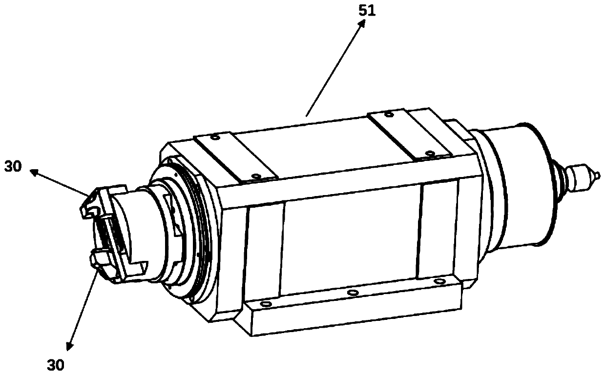
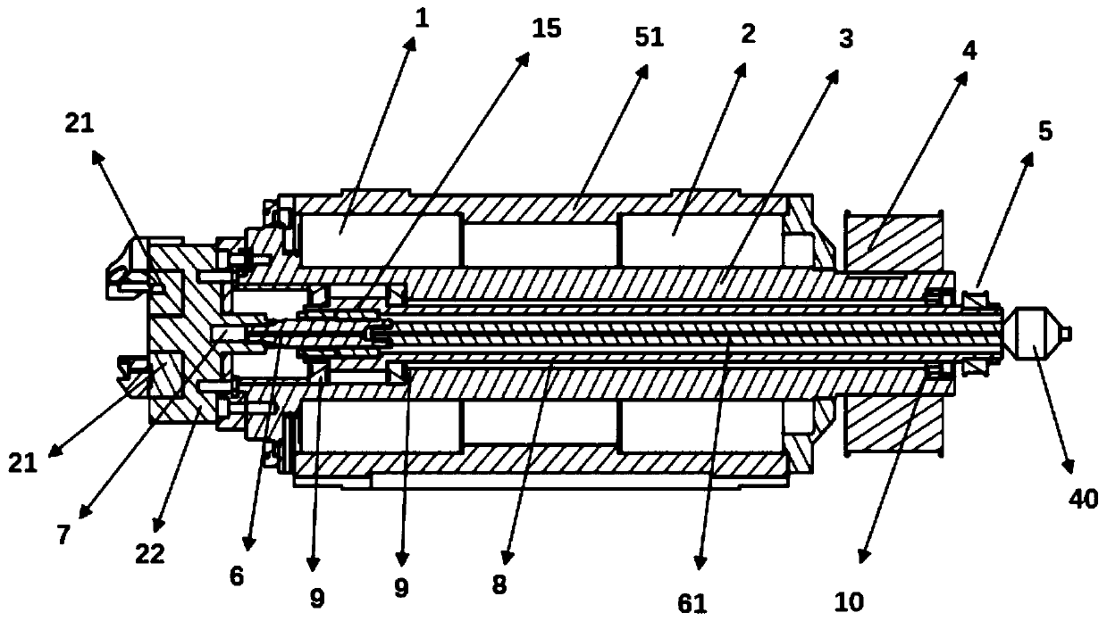
[0018] Example: as attached figure 1 , 2 As shown, the structure of the tool spreading power head mainly includes a main shaft 3, a screw rod 6, a slider 7, a tool spreading disc 22 and a main shaft housing 51, and the main shaft 3 is supported on the main shaft housing through the main shaft bearing A1 and the main shaft bearing B2. On the body 51, the external driving mechanism drives the main shaft 3 to rotate through the drive pulley 4 installed at the rear end of the main shaft 3, thereby driving the tool 30 mounted on the spreading tool disc 22 at the front end of the main shaft 3 to rotate to achieve the main drive for cutting; The slider 7 is set in the center of the spreader cutter head 22 and can move forward and backward along the axis of the main shaft 3. The helical tooth structure on both sides of the slider 7 drives the radial cutter body slide rail 21 to move radially, and the cutter body slide rail 21 Drive the tool 30 installed thereon to realize the radial ...


PUM


Abstract

The invention discloses a generating tool power head structure, and relates to the field of machine tool parts. The generating tool power head structure mainly comprises a main shaft, a screw rod, a sliding block, a generating tool cutterhead and a main shaft box body, wherein the main shaft is supported on a main shaft box body through two main shaft bearings, and an external driving mechanism drives the main shaft to rotate through a driving belt wheel to drive a tool on the generating tool cutterhead to rotate; a sliding block which can move back and forth along the axial direction of the main shaft is arranged in the center of the generating tool cutterhead, inclined tooth structures on the two sides of the sliding block drive a radial tool body sliding rail to move radially, and the cutter body sliding rail drives the tool installed thereon to achieve radial adjustment of the tool. The generating tool power head structure has the beneficial effects that the structure is simple, the main shaft conforms to the machine tool standard, the automatic lubricating function is achieved through a rotary oil distributing end, the generating tool driving rigidity is extremely high, and the guarantee is provided for high precision and large margin cutting, the heat influence of a generating tool driving mechanism and the main shaft is extremely small, the influence on machining precision is extremely small, and subsequent measurement compensation requirements can be greatly reduced on the control of a generating tool.

Description

technical field [0001] The invention relates to the field of machine tool components, in particular to a structure of a tool spreading power head. Background technique [0002] The driving mode of the existing cutter head adopts the proportional servo hydraulic cylinder fixed on the slide table at the rear end of the main shaft to transmit the push and pull force of the oil cylinder to the pull rod of the cutter head through the isolated rotating bearing group for driving, or it is replaced by a screw nut slide table The proportional hydraulic servo cylinder is realized by driving the cutter head pull rod to move back and forth through the angular thrust bearing. [0003] The existing design has the following defects: the driving structure is relatively large, especially the axial rear end requires a long driving part, and the volume ratio is large; the pulling force of the tie rod needs to be driven by the pull rod of the main shaft, and the drive chain is closed by the mai...

Claims


Application Information

Patent Timeline
Patent Type & Authority Applications(China)
IPC IPC(8): B23Q5/34B23B19/02B23Q11/12
CPCB23Q1/70B23Q5/34B23Q11/12B23Q11/121
Inventor 方国平姚礼军张银桥付梅军
Owner WANXIANGQIANCHAO CO LTD
Why Eureka
Try Eureka