
Centrifugal extractor with stirring, mixing and feeding functions

A centrifugal extractor, stirring and mixing technology, used in mixers, mixing methods, solvent extraction, etc., can solve the problems affecting the process of centrifugal separation, spillover, poor mixing uniformity, etc., to prevent spillage, avoid accumulation, and high mixing. The effect of uniformity

Pending Publication Date: 2020-03-13
苏州增华新能源科技有限公司
View PDF1 Cites 6 Cited by
  • Summary
  • Abstract
  • Description
  • Claims
  • Application Information

AI Technical Summary

Problems solved by technology

[0004] In the prior art, most of the centrifugal extractors adopt the mixed feeding structure of the traditional annular centrifugal extractor. Due to its own disadvantages, for example, the light phase and the heavy phase are prone to emulsification during the mixing process, which affects the subsequent The process of centrifugal separation, and the mixing intensity is not easy to control, and the power consumption is relatively large. For this reason, Chinese invention patent CN206700839U discloses a centrifugal extractor mixing feeding device, which includes a shell, a light phase feeding port, a heavy phase feeding Material inlet, drum, motor shaft, driving motor, the motor shaft extends to the lower end of the drum, the drum is fixed on the motor shaft, the shell is fixed on the outside of the drum, the lower part of the shell is connected with a mixing chamber, the mixing chamber and the drum The middle position of the bottom is provided with a sealed impeller, the mixing chamber is provided with a mixing impeller, and the bottom of the mixing chamber is connected with a light-phase feeding port and a heavy-phase feeding port symmetrically fed in a radial direction; the present invention adopts an impeller to mix The structure replaces the traditional annular gap mixing feed structure, which can effectively control the mixing intensity and avoid the emulsification problem caused by the excessive mixing intensity caused by the traditional structure.
Although the sealing impeller was added in order to prevent the mixture from overflowing, but with the increase of the start-up time, the matching relationship between the sealing impeller and the shell becomes worse, which will inevitably lead to overflow, which reduces the impact to a certain extent. The working performance of the centrifugal extractor; secondly, the stirring and mixing uniformity of the above-mentioned mixing and feeding device is slightly poor, which cannot meet the mixing requirements of fine materials. Therefore, it is urgent for technicians to solve the above problems

Method used


Image

  • Centrifugal extractor with stirring, mixing and feeding functions
  • Centrifugal extractor with stirring, mixing and feeding functions
  • Centrifugal extractor with stirring, mixing and feeding functions

Examples


Embodiment Construction

[0028] In the description of the present invention, it should be understood that the orientation or positional relationship indicated by the terms "upper", "lower", etc. is based on the orientation or positional relationship shown in the drawings, and is only for the convenience of describing the present invention and simplifying the description. It is not intended to indicate or imply that the referred device or element must have a particular orientation, be constructed in a particular orientation, and operate in a particular orientation, and thus should not be construed as limiting the invention.

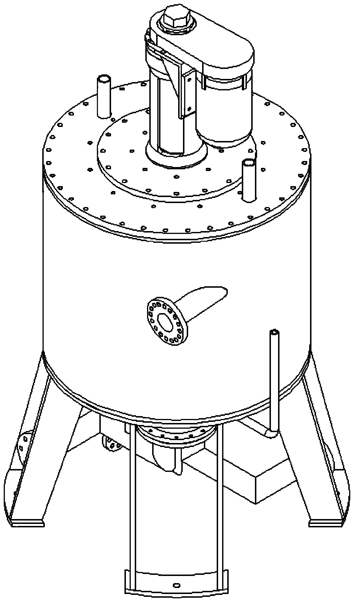
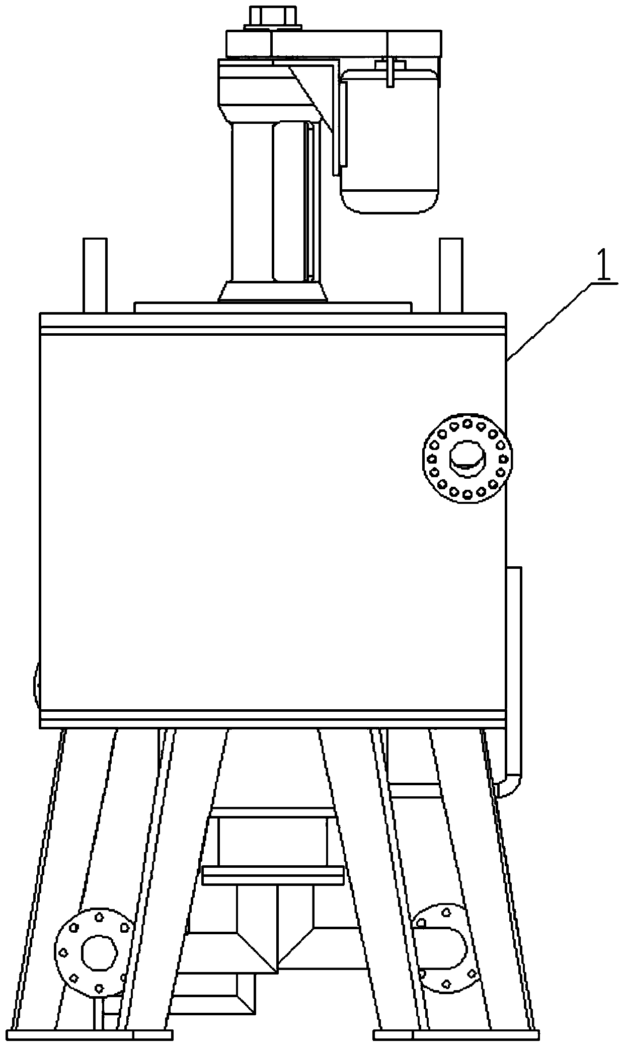
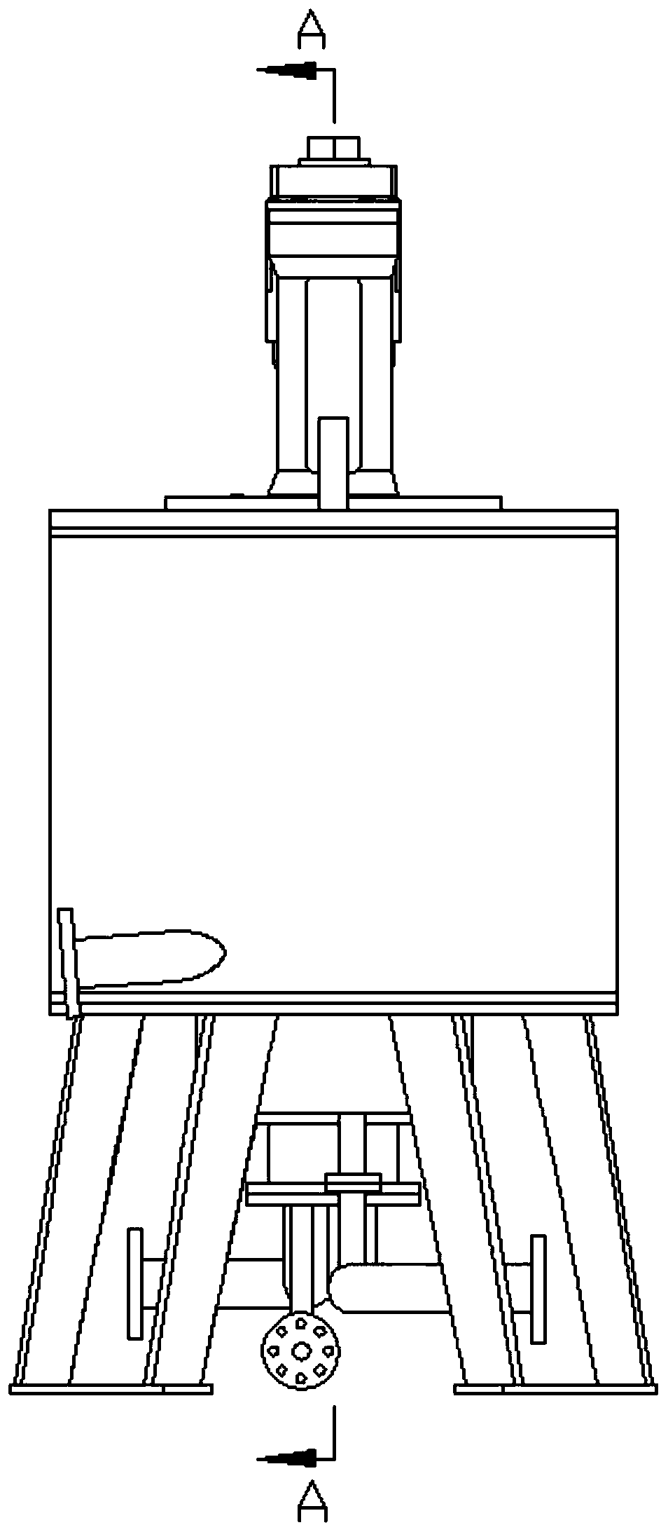
[0029] Below in conjunction with specific embodiment, content of the present invention is described in further detail, figure 1 , figure 2 , image 3 , Figure 4 The three-dimensional schematic view, front view, left view and A-A sectional view of the first embodiment of the centrifugal extractor with the function of stirring and mixing feed in the present invention are respect...


PUM


Abstract

The invention relates to a centrifugal extractor with stirring, mixing and feeding functions. The centrifugal extractor comprises a shell, a rotary drum extraction unit and a stirring and mixing unit.The rotary drum extraction unit comprises a power shaft and a rotary drum. The stirring and mixing unit is arranged just below the rotary drum extraction unit and comprises a stirring and mixing chamber, a first stirring blade assembly and a second stirring blade assembly with a certain lead angle. The stirring and mixing chamber is directly communicated with the inner cavity of the rotary drum.The power shaft extends into the inner cavity of the stirring and mixing chamber. The first stirring blade assembly and the second stirring blade assembly are both arranged in the stirring and mixingchamber and are driven by the power shaft at the same time. A light phase and a heavy phase are fully mixed in the stirring and mixing chamber, and a liquid-liquid mixed liquid is lifted under the action of the second stirring blade assembly to enter the inner cavity of the rotary drum in time, so that the mixing uniformity of the light phase and the heavy phase is ensured, the accumulation of theliquid-liquid mixed liquid in the stirring and mixing chamber is avoided, and the overflow phenomenon is avoided.

Description

technical field [0001] The invention relates to the technical field of centrifugal extractor manufacturing, in particular to a centrifugal extractor with the function of stirring, mixing and feeding. Background technique [0002] Centrifugal extraction technology is a practical technology that realizes liquid-liquid two-phase contact mass transfer and phase separation with the help of centrifugal force field. It is a new type of high-efficiency separation technology that combines liquid-liquid extraction and centrifugal technology. Compared with other extraction technologies It has the characteristics of short contact time of two-phase materials, fast phase separation speed, small storage amount in the equipment, and wide operation range. This technology has been used by a large number of scientific researchers in many fields such as hydrometallurgy, pharmaceuticals, wastewater treatment, nuclear energy, petrochemicals, and fine chemicals. [0003] Centrifugal extraction te...

Claims


Application Information

Patent Timeline
Patent Type & Authority Applications(China)
IPC IPC(8): B01D11/04B01D17/038B01F13/10B01F3/08
CPCB01D11/0476B01D17/0217B01F23/43B01F33/82
Inventor 朱永长雷玉平肖华平赵起
Owner 苏州增华新能源科技有限公司
Learn More