
Welding and welding joint surface layer performance improvement double-heat-source combined effect method

A joint action, dual heat source technology, applied in welding equipment, welding equipment, auxiliary welding equipment, etc., can solve the problems of corrosion resistance and wear resistance of the weld position, and achieve weld performance improvement, repair and corrosion resistance performance, enhance the effect of using functions

Inactive Publication Date: 2020-03-13
TAIYUAN UNIV OF TECH
View PDF5 Cites 0 Cited by
  • Summary
  • Abstract
  • Description
  • Claims
  • Application Information

AI Technical Summary

Problems solved by technology

[0003] The purpose of the present invention is to provide a joint action method of welding and improving the performance of the surface layer of the weld with dual heat sources, to solve the problem of the corrosion resistance and wear resistance of the weld position after welding stainless steel, wear-resistant steel and other materials, and to provide A dual heat source joint action method for improving welding and weld surface performance

Method used


Image

  • Welding and welding joint surface layer performance improvement double-heat-source combined effect method

Examples


Embodiment 1

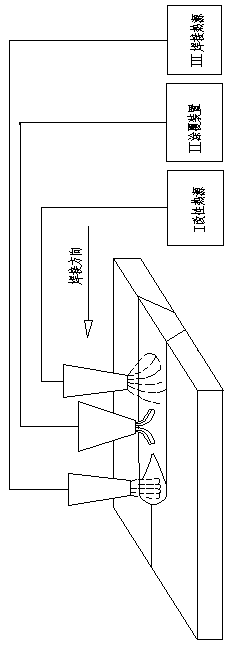
[0016] combine figure 1 This embodiment is described. The joint action method of welding and weld surface performance improvement with dual heat sources in this embodiment is mainly composed of welding heat source, weld surface performance improvement heat source and weld performance improvement material coating device. Along the welding direction, the welding heat source is at In the front, the material coating device for improving weld performance is in the middle, and the heat source for improving weld surface performance is behind. The movement speed of the three is the same during welding, and the relative position does not change.

Embodiment 2

[0018] combine figure 1 To illustrate this embodiment, during the action process, the front heat source completes the welding of the weld seam according to the welding process, and after the weld seam is formed; the intermediate coating device coats the performance material on the surface of the weld seam; role, thereby improving weld performance.

Embodiment 3

[0020] combine figure 1 In this embodiment, the material coated by the material coating device is determined according to the process requirements. It can be a solid powder, a sticky soft layer, or a thin strip plate. When the heat source heats the coated material, a layer with good stability is formed. Preferably, the heating method and energy density are determined according to the process requirements. Generally, the heat source can be argon arc heat, laser, plasma heat, induction heat, etc.


PUM


Abstract

The invention relates to a welding and welding joint surface layer performance improvement double-heat-source combined effect method. When materials such as stainless steel and abrasion-resistant steel are welded, due to the heat effect in the welding process, welding joint components, structures and the like are changed, original corrosion resistance, abrasion resistance and the like are loweredor even disappear, consequently, performance of a welding joint part is not matched with that of a base material, and the application range is limited. According to the welding and welding joint surface layer performance improvement double-heat-source combined effect method, a welding heat source, a welding joint surface layer performance improvement heat source and a welding joint performance improvement material coating device are mainly included. In the welding direction, the welding heat source conducts connector welding to form a welding joint; the performance improvement material coatingdevice is arranged behind for material coating; and the welding joint surface layer performance improvement heat source is arranged behind to provide heat to heat the coated material which acts withthe welding joint surface layer to form the welding joint surface layer meeting the requirements.

Description

Technical field: [0001] The invention relates to a joint action method of double heat sources for welding and improving the performance of the surface layer of the weld. Background technique: [0002] When stainless steel, wear-resistant steel and other materials are welded, due to the thermal action of the welding process, the composition and structure of the weld will change, and the original corrosion resistance and wear resistance will decrease or even disappear, resulting in the performance of the weld part being different from that of the base metal. matching, which limits its scope of application. In order to solve this problem, a joint action method of welding and weld surface performance improvement with dual heat sources was invented. Invention content: [0003] The purpose of the present invention is to provide a joint action method of welding and improving the performance of the surface layer of the weld with dual heat sources, to solve the problem of the corr...

Claims


Application Information

Patent Timeline
IPC IPC(8): B23K31/02B23K37/00B05D3/02B05D5/08B05D7/24
CPCB05D3/0254B05D5/08B05D7/24B23K31/02B23K37/00
Inventor 徐娜杨景轩张兴芳韩春花王玉乔
Owner TAIYUAN UNIV OF TECH
Learn More