
Oil-gas lubrication mixing device and working method thereof

A technology of mixing equipment and oil and gas lubrication, applied in mixing methods, mixers, mechanical equipment, etc., can solve the problems of oil and gas injection, insufficient transmission rate, affecting the stability of oil and gas mixing, and uncontrollable amount of lubricating oil, to prevent lubrication Oil return and air leakage, excellent sealing effect, stable oil and gas mixing effect

Active Publication Date: 2020-03-13
灵璧县浩翔信息科技有限公司
View PDF10 Cites 1 Cited by
  • Summary
  • Abstract
  • Description
  • Claims
  • Application Information

AI Technical Summary

Problems solved by technology

[0004] The object of the present invention is to provide a kind of oil-gas lubrication mixing equipment and its working method to solve the following technical problems: (1) the first air pump delivers air to the air valve through the first air pipe, and the second air pump sends air through the second air pipe To the parallel air valve, the air in the parallel air valve is transmitted to the two air distribution pipes respectively, and is transmitted to the air pipe three-way valve through the pneumatic coupler on the two air distribution pipes, and the air is transmitted to the air pipe three-way valve through the air pipe three-way valve. Through the main air passage, it finally enters the mixing chamber in the mixer, solving the technical problems that the lack of air pressure in the oil and gas mixing equipment in the prior art will affect the stability of the oil and gas mixing, and at the same time, the injection and transmission rate of the mixed oil and gas are insufficient; ( 2) The oil in the oil tank is extracted through the lubricating oil inlet through two oil pumps, and the lubricating oil is transferred to the limit cap through the pipe fittings. The solenoid valve opens the oil volume adjustment chamber, and the limit rod moves in the oil volume adjustment chamber. The lubricating oil is pressed into the oil inlet channel through the piston, and then the lubricating oil enters the mixing chamber. Through this setting, the limit rod of different lengths can The design controls the flow of lubricating oil. After the lubricating oil is added, the solenoid valve of the oil circuit is closed, and the sealing ring on the piston seals the oil volume adjustment cavity to prevent the lubricating oil from flowing back. By setting three equally spaced sealing rings on the piston, the oil volume The sealing effect is better when the adjustment chamber is closed, which effectively prevents lubricating oil backflow and air leakage, and solves the problem of unstable lubricating oil pressure when lubricating oil is supplied in the prior art, and at the same time, the amount of lubricating oil cannot be controlled, and the channel is sealed after the supply channel is closed If the effect is not good, it will easily cause technical problems of backflow; (3) Lubricating oil and air are mixed in the mixing chamber, and after mixing, they are blown into the mixing pressure valve, and then enter the oil and gas injection pipe through the mixing pressure valve, and adjust the mixing pressure valve to adjust the oil and gas The oil and gas throughput of the injection pipe, the mixed oil and gas enters the three-way through the oil-gas injection pipe, and then enters the two oil-gas branch pipes through the three-way respectively, observes the internal pressure of the oil-gas branch pipes through the oil-gas pressure gauge, and controls the pressure in the oil-gas branch pipes through the oil-gas control valve. The flow rate is controlled to prevent the waste caused by the excessive overflow caused by the fast speed and large flow of the mixed oil and gas. Oil and gas pass through the oil and gas inlet holes on the bearing end cover to lubricate the drive shaft, solving the problem that too much mixed oil and gas in the prior art will affect the transmission speed of the drive shaft, and at the same time, the effect of adding mixed oil and gas is not ideal, and it cannot evenly affect the drive shaft The technical problem of lubricating at the end

Method used


Image

  • Oil-gas lubrication mixing device and working method thereof
  • Oil-gas lubrication mixing device and working method thereof
  • Oil-gas lubrication mixing device and working method thereof

Examples


Embodiment Construction

[0033] The following will clearly and completely describe the technical solutions in the embodiments of the present invention with reference to the accompanying drawings in the embodiments of the present invention. Obviously, the described embodiments are only some, not all, embodiments of the present invention. Based on the embodiments of the present invention, all other embodiments obtained by persons of ordinary skill in the art without creative efforts fall within the protection scope of the present invention.

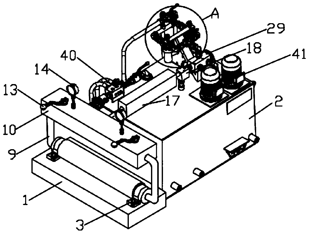
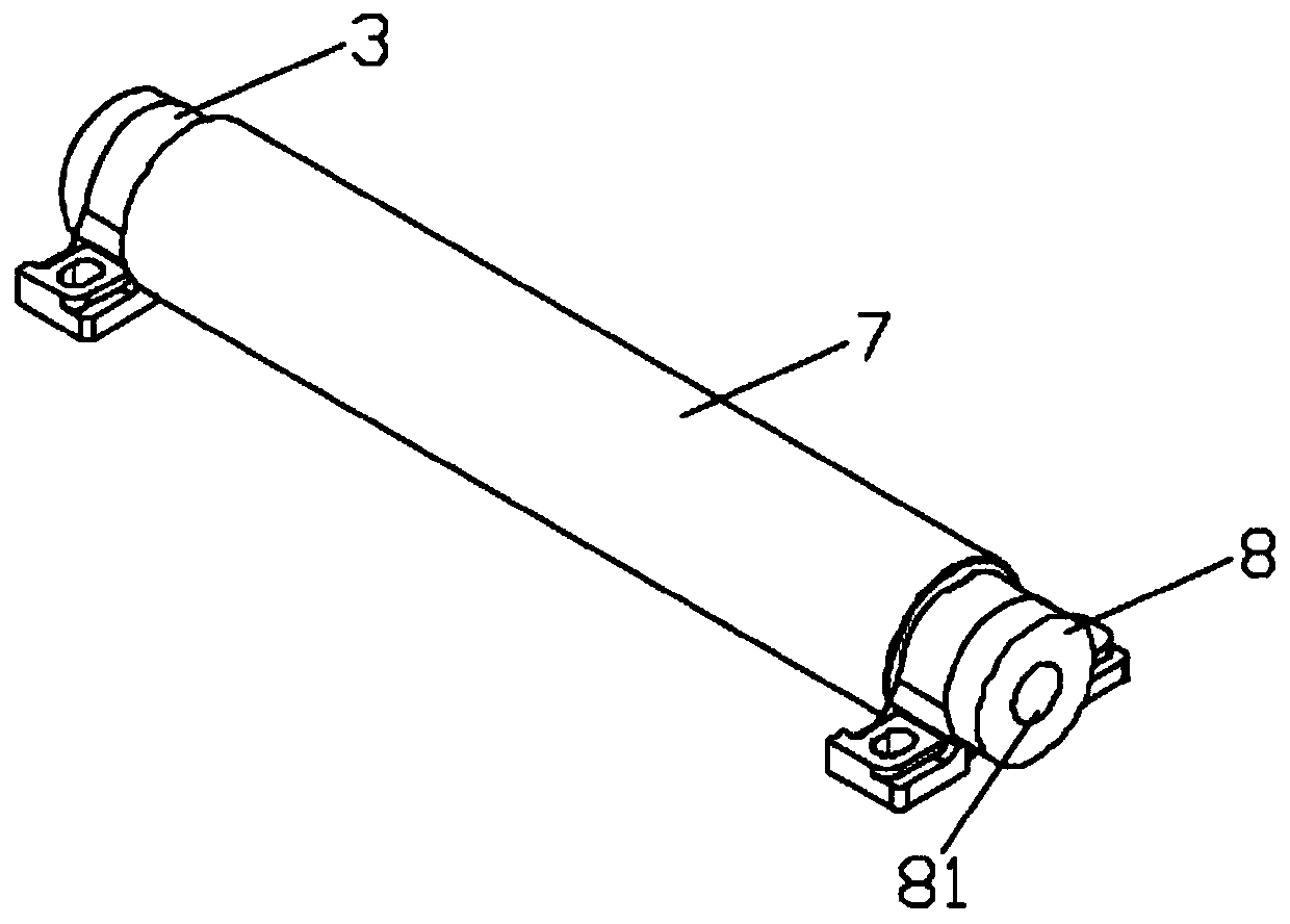
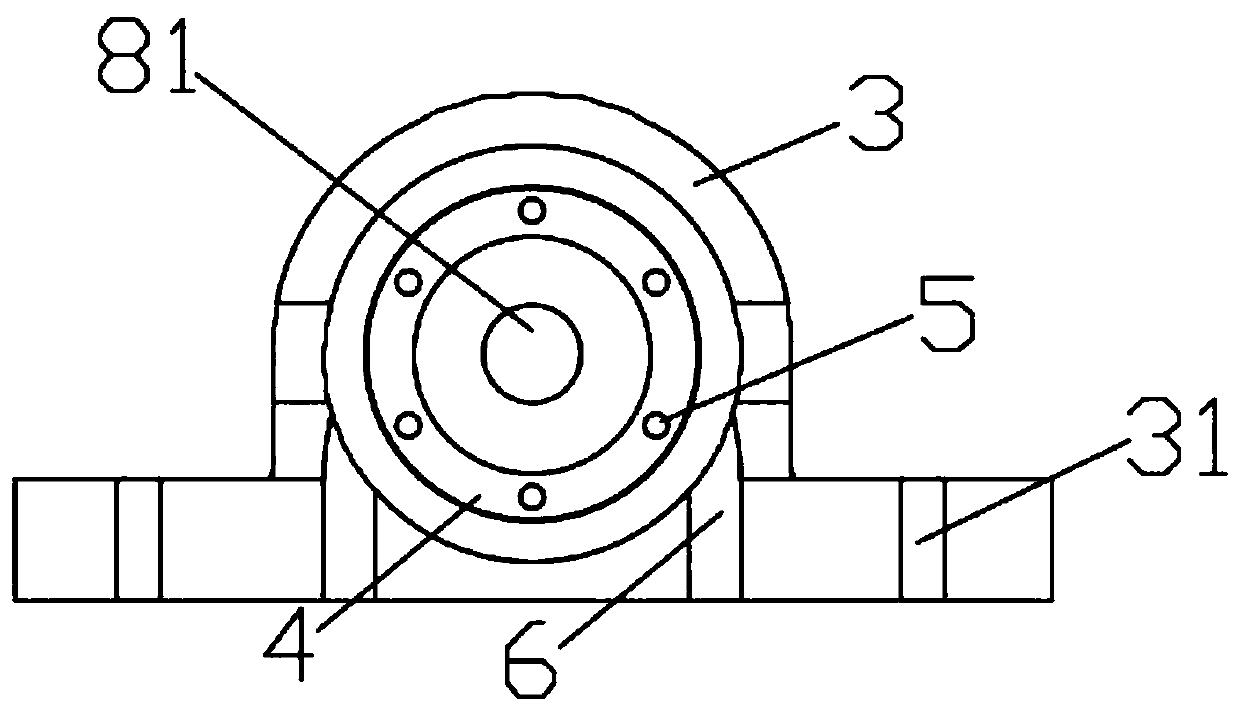
[0034] see Figure 1-7 As shown, the present invention is a kind of oil-gas lubrication mixing equipment, which includes a mounting table 1, an oil tank 2 is arranged on one side of the mounting table 1, and two bearing blocks 3 are fixedly installed on the top of the mounting table 1, and the transmission connection between the two bearing blocks 3 There is a transmission shaft 7, two oil spill holes 6 are opened at the bottom of the bearing seat 3, a seat cover 8...


PUM


Abstract

The invention discloses an oil-gas lubrication mixing device and a working method thereof. The device comprises a mounting table, a fuel tank is arranged on one side of the mounting table, two bearingseats are fixedly installed on the top of the mounting table, a transmission shaft is in transmission connection between the two bearing seats, and the bottom of each bearing seat is provided with two oil spill holes; and a seat cover is installed at one end, far away from the transmission shaft, of each bearing seat, and the surface of each seat cover is provided with an annular through hole. According to the device, a first air pump delivers air to an air combining valve through a first air pipe, a second air pump delivers air to the air combining valve through a second air pipe, the air inthe air combining valve is respectively transmitted to two air distributing pipes and is transmitted to an air pipe three-way valve through pneumatic two-combination members of two air distributing pipes, and the air is transmitted to an air combining pipe through the air pipe three-way valve and finally enters a mixing chamber in a mixer through a main air passage, so that the technical problemsthat during oil-gas mixing in an oil-gas mixing device in the prior art, if air pressure is insufficient, the stability of the oil-gas mixing is affected, and the injection and transmission rate of oil and gas are insufficient after mixing are solved.

Description

technical field [0001] The invention relates to the technical field of oil-gas mixing, in particular to an oil-gas lubrication mixing device and a working method thereof. Background technique [0002] Oil-air lubrication, known as "air-liquid two-phase fluid cooling lubrication technology" in academia, is a new type of lubrication technology, which has incomparable advantages compared with traditional single-phase fluid lubrication technology. It successfully solves the insurmountable problems of dry oil lubrication and oil mist lubrication, and is a blooming magnificent flower in lubrication technology. It adapts to the needs of the latest development of machinery and industrial equipment, especially suitable for high temperature, heavy load, high speed, extremely low speed and harsh working conditions with cooling water and dirt intruding into the lubricating point. [0003] The patent document (CN200520043891.5) discloses a spray lubrication device, which adopts the prin...

Claims


Application Information

Patent Timeline
IPC IPC(8): F16N7/30F16N27/02F16N29/00F16N31/00B01F3/04B01F15/02
CPCF16N7/30F16N27/02F16N29/00F16N31/00F16N2210/14F16N2270/20F16N2280/02B01F23/29B01F35/718051B01F35/71B01F2101/39
Inventor 王巧云
Owner 灵璧县浩翔信息科技有限公司
Learn More