Method for reinforcing smelting effect of bottom blowing smelting furnace and avoiding melt splashing

A smelting furnace and bottom blowing furnace technology, applied in the field of bottom blowing smelting, can solve the problems of large metal loss rate, low smelting efficiency, serious splashing and the like

Active Publication Date: 2020-03-17
UNIV OF SCI & TECH BEIJING
View PDF8 Cites 0 Cited by
  • Summary
  • Abstract
  • Description
  • Claims
  • Application Information

AI Technical Summary

Problems solved by technology

[0004] Aiming at the problems of uneven gas injection and stirring, serious splashing, low smelting efficiency, and high metal loss rate in a large bottom-blowing smelting furnace, different spray gun arrangements were proposed, and process parameters and equipment parameters were optimized to achieve improved The purpose of smelting efficiency, suppressing splashing, reducing the circulation of metal in slag, and improving the production capacity of bottom blowing furnace

Method used


Image

  • Method for reinforcing smelting effect of bottom blowing smelting furnace and avoiding melt splashing
  • Method for reinforcing smelting effect of bottom blowing smelting furnace and avoiding melt splashing
  • Method for reinforcing smelting effect of bottom blowing smelting furnace and avoiding melt splashing

Examples


Embodiment 1

[0032] Embodiment 1 (cross-flow injection):

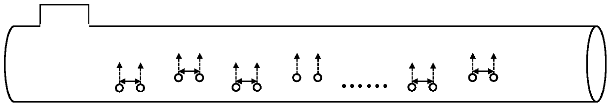
[0033] Taking an implementation of cross-flow blowing as an example (this example is to change the axial distance of the spray guns), all the spray guns of the bottom blowing furnace are numbered sequentially from the side close to the smoke exhaust port to ensure that the total air supply volume and the diameter of the spray guns are not changed. Change, and the air pressure or air supply volume of each spray gun is equal. A group of fans is used to supply air to two groups of spray guns, and the axial distance between odd-numbered spray guns and even-numbered spray guns is changed, so that the airflow distance injected into the melt by each adjacent two spray guns increases, and the airflow superposition effect becomes weaker, resulting in " "Cross-flow blowing" effect, the original spacing is 380mm, in this example the adjusted spacing is 610mm.

[0034] Solve the flow field in the furnace under the two working conditions throu...

Embodiment 2

[0035] Embodiment 2 (staggered peak injection):

[0036] Taking an implementation of staggered peak injection as an example (this example is to change the ratio of spray gun diameters), all the spray guns of the bottom blowing furnace are numbered sequentially from the side close to the smoke exhaust port, and a group of fans are used to supply air to the two groups of spray guns , to ensure that the total air supply volume, the total spray area and the outlet end pressure of each spray gun are the same, and by changing the diameter ratio of the odd and even two sets of spray guns, each adjacent two spray guns are sprayed into the melt with different airflow intensities, resulting in " Peak staggered injection" effect, the area ratio is 1:1 under the original working condition, now it is adjusted to 1.2:0.8, and the diameter ratio is 1.095:0.894.

[0037] Solve the flow field in the furnace under the two working conditions through numerical simulation, take the melt in the sti...

Embodiment 3

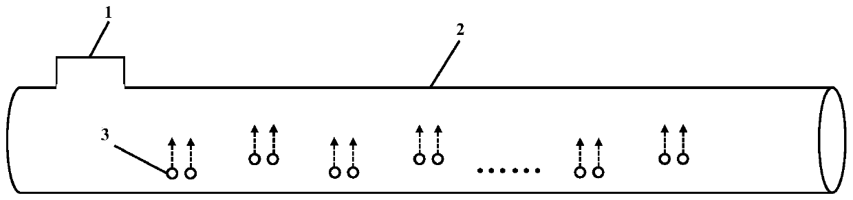
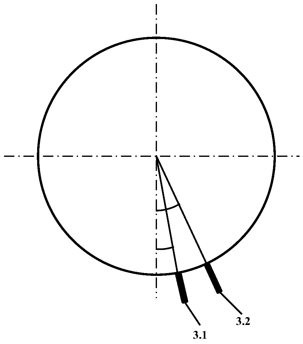
[0039] Taking a copper bottom blowing furnace as an example, there are 14 groups of spray guns on the same side of the center near the bottom of the furnace body. Every two spray guns form a group, with a total of 28 spray guns. The adjacent two groups of spray guns are arranged alternately. The 14 groups of spray guns are numbered sequentially from the side close to the smoke exhaust port, the angles of the 7 odd groups of spray guns can be adjusted from 6 to 12°, and the angles of the 7 even groups of spray guns can be adjusted from 21 to 27°. The distance between the two spray guns in each group is 380-610mm, and the distance between two adjacent groups of spray guns is 1150mm. Vertical to the wall of the furnace body, the airflow is blown into the furnace vertically from the outlet of the spray gun. A simple schematic diagram of a bottom-blown melting furnace figure 1 .


PUM


Abstract

The invention discloses a method for reinforcing a smelting effect of a bottom blowing smelting furnace and avoiding melt splashing, and belongs to the technical field of bottom blowing smelting furnaces. The method comprises the steps of cross flow blowing and peak staggering blowing which are used in a combined manner. The cross flow blowing ensures that under the condition that the blowing strength of each set of adjacent blowing guns is the same, the positions of the blowing guns are changed, states of two adjacent strands of blowing airflows generate the difference, and the aims of relieving airflow overlaying, restraining splashing and reinforcing blowing can be achieved; and peak staggering blowing ensures that under the condition that the positions of each set of adjacent blowing guns are same, the blowing strength is changed, the difference is generated between states of two adjacent strands of blowing airflows, and the aims of relieving airflow overlaying, restraining splashing and reinforcing blowing can be achieved. Through the method, melt stirring in the bottom blowing furnace is more uniform, furnace charge is promoted to have a complete reaction, it is prevented that furnace slag generated by bottom blowing smelting includes metal and a raw material, the melt surface layer splashing is avoided, the too concentrated washing stress borne by the wall face close tothe blowing guns can be weakened, and the capacity of the bottom blowing smelting furnace can be improved.

Description

technical field [0001] The invention belongs to the technical field of bottom blowing smelting, and in particular relates to a method for enhancing the smelting effect of a bottom blowing smelting furnace and improving melt splashing. Background technique [0002] Bottom blowing furnace smelting technology was originally applied in converter steelmaking to remove sulfur, phosphorus, silicon and other impurities in molten iron and control carbon content, and has been widely used in the steel industry all over the world. In view of the successful application and many advantages of oxygen-enriched bottom blowing smelting technology in steelmaking, it has gradually been widely used in lead smelting, copper smelting and other fields. It has the characteristics of strong adaptability to raw materials, high efficiency, energy saving, and environmental protection. [0003] Some of the existing copper bottom-blowing furnaces and bottom-blowing smelting processes have problems such as...

Claims


Application Information

Patent Timeline
Patent Type & Authority Applications(China)
IPC IPC(8): C22B15/00
CPCC22B15/003
Inventor 赵洪亮穆亮照王成彦刘风琴王玲张文娟马保中
Owner UNIV OF SCI & TECH BEIJING
Why Eureka
Try Eureka