
A preparation method of co-heating multiple monomers for thermal battery

A thermal battery and monomer technology, applied in the direction of delayed action cells, etc., can solve problems such as the use of ultra-thin single chips, high heat, and reduced mechanical strength, so as to optimize the structure of thermal battery cells and avoid thermal mismatch , Improve the effect of mechanical strength

Active Publication Date: 2021-01-05
GUIZHOU MEILING POWER SUPPLY CO LTD
View PDF12 Cites 0 Cited by
  • Summary
  • Abstract
  • Description
  • Claims
  • Application Information

AI Technical Summary

Problems solved by technology

[0004] The methods disclosed in the above documents and other existing technologies can prepare ultra-thin single sheets of thermal batteries, and the specific power of thermal batteries can also be improved. However, due to the thickness, the impact resistance of the single sheets is greatly weakened, and the mechanical strength decreases. It has seriously affected the application of thermal batteries prepared by these advanced processes in high overload fields
Moreover, due to the flammable and explosive characteristics of the heating powder in the thermal battery, the space requirements for the preparation of the new process are relatively strict, and at the same time, the safety hazard is relatively large, so it is not suitable for these ultra-thin monolithic preparation processes
However, the traditional heating sheet cannot be used with the ultra-thin single sheet due to the high heat due to the large number of active material sheets.

Method used


Image

  • A preparation method of co-heating multiple monomers for thermal battery
  • A preparation method of co-heating multiple monomers for thermal battery
  • A preparation method of co-heating multiple monomers for thermal battery

Examples


Embodiment 1

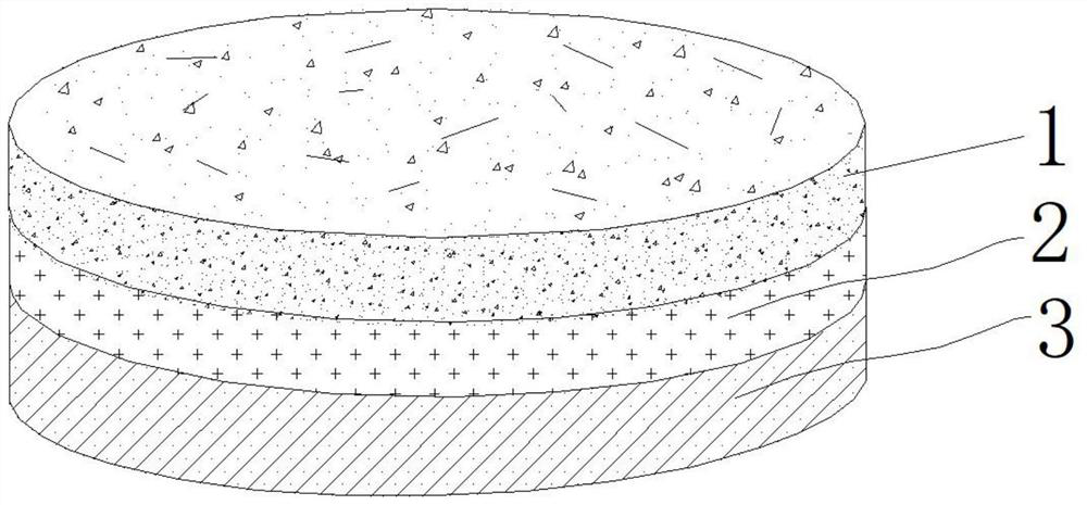
[0038] Such as figure 1 , figure 2 As shown, a preparation method of co-heating multi-monomer for thermal battery, said co-heating multi-monomer is composed of multi-monomer layer (1), buffer layer (2) and heating layer (3), the co-heating multi-monomer The preparation method of the monomer includes the preparation of a heating sheet, a buffer heating sheet, positive and negative electrodes, a separator and a co-heating multi-monomer, specifically including the following steps;

[0039] ①Preparation of the heating sheet: Pour the heating powder of the thermal battery into the mold, apply a pressure of 10KN to form the heating sheet (8); the diameter of the groove of the mold is 8mm;

[0040] ②Preparation of the buffer heating sheet: spray a conductive adhesive on the surface of the heating sheet (8) prepared in step ①, and then stick the buffer layer (2) on the surface of the heating sheet (8) to obtain a buffer heating sheet;

[0041] The buffer layer (2) is a graphite sub...

Embodiment 2

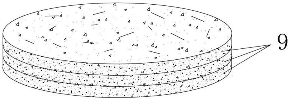
[0048] Such as figure 1 , image 3 As shown, a preparation method of co-heating multi-monomer for thermal battery, said co-heating multi-monomer is composed of multi-monomer layer (1), buffer layer (2) and heating layer (3), the co-heating multi-monomer The preparation method of the monomer includes the preparation of a heating sheet, a buffer heating sheet, positive and negative electrodes, a separator and a co-heating multi-monomer, specifically including the following steps;

[0049] ①Preparation of the heating sheet: Pour the heating powder of the thermal battery into the mold, apply a pressure of 1200KN to form the heating sheet (8); the diameter of the groove of the mold is 130mm;

[0050] ②Preparation of the buffer heating sheet: spray a conductive adhesive on the surface of the heating sheet (8) prepared in step ①, and then stick the buffer layer (2) on the surface of the heating sheet (8) to obtain a buffer heating sheet;

[0051] The buffer layer (2) is a high ther...

Embodiment 3

[0058] Such as figure 1 , Figure 4 As shown, a preparation method of co-heating multi-monomer for thermal battery, said co-heating multi-monomer is composed of multi-monomer layer (1), buffer layer (2) and heating layer (3), the co-heating multi-monomer The preparation method of the monomer includes the preparation of a heating sheet, a buffer heating sheet, positive and negative electrodes, a separator and a co-heating multi-monomer, specifically including the following steps;

[0059] ①Preparation of the heating sheet: Pour the heating powder of the thermal battery into the mold, apply a pressure of 560KN to form the heating sheet (8); the diameter of the groove of the mold is 60mm;

[0060] ②Preparation of the buffer heating sheet: spray a conductive adhesive on the surface of the heating sheet (8) prepared in step ①, and then stick the buffer layer (2) on the surface of the heating sheet (8) to obtain a buffer heating sheet;

[0061] The buffer layer (2) is metal foil; ...


PUM

PropertyMeasurementUnit
diameteraaaaaaaaaa
thicknessaaaaaaaaaa
thicknessaaaaaaaaaa

Abstract

The invention discloses a preparation method of a co-heating multi-monomer for a thermal battery. The co-heating multi-monomer is composed of a multi-monomer layer (1), a buffer layer (2) and a heating layer (3), and the preparation method comprises the preparation of a heating sheet, a buffer heating sheet, a positive electrode, a negative electrode, a diaphragm and the co-heating multi-monomer.According to the co-heating multi-monomer for the thermal battery, the multiple monomers are molded at one time, so that the mechanical strength of an ultra-thin single sheet can be improved, and theapplication of the ultra-thin single sheet process in the field of high overload is facilitated. The heating mode of a traditional thermal battery monomer is changed from one-to-one heating to one-to-many heating to optimize the structure of the thermal battery monomer, so that the efficiency is improved, and the problem that the heating sheet is not matched with the heat of the ultrathin monomeris avoided. By a rotary blade-coating mode, the ultrathin insulating layers are blade-coated between the positive electrode and the diaphragm and between the diaphragm and the negative electrode in the monomers and between the multiple monomers, and the ultrathin insulating layers and the multiple monomers form an organic entirety, so that the short circuit problem of the ultrathin monomers is avoided, and the safety of the ultrathin heat supply multi-monomer battery is greatly improved.

Description

technical field [0001] The invention belongs to the technical field of thermal battery preparation, and in particular relates to a method for preparing co-heating multi-monomers for thermal batteries. Background technique [0002] Thermal battery is a heat-activated reserve battery. When stored at room temperature, the electrolyte is a non-conductive solid. When in use, an electric ignition head or a firing pin mechanism is used to ignite the heating agent inside, so that the electrolyte melts into an ion conductor and is activated. A reserve battery, the storage time is theoretically unlimited, and the actual measurable value is more than 17 years. Due to its small internal resistance, wide operating temperature range, long storage time, quick and reliable activation, and no maintenance, it has developed into an ideal power supply for modern weapons. [0003] With the rapid development of the field of thermal batteries, the preparation method of thermal battery single piec...

Claims


Application Information

Patent Timeline
Patent Type & Authority Patents(China)
IPC IPC(8): H01M6/36
CPCH01M6/36
Inventor 孟剑赵洪楷盛德卫万伟华王京亮李云伟刘琪
Owner GUIZHOU MEILING POWER SUPPLY CO LTD
Learn More