
Automatic feeding mechanism and method for miniature machine tool

A technology of automatic feeding and machine tools, applied in the direction of metal processing machinery parts, metal processing equipment, feeding devices, etc., can solve the problems of lack of stability, impractical micro machine tools, and no effective and practical feeding mechanism for micro machine tools, etc., to achieve The operation is clear and light, and the effect of reducing the production cost

Pending Publication Date: 2020-03-24
江苏一首机械科技有限公司
View PDF0 Cites 0 Cited by
  • Summary
  • Abstract
  • Description
  • Claims
  • Application Information

AI Technical Summary

Problems solved by technology

[0003] The purpose of the present invention is to solve the problem that the micro-machine tools on the market are not practical, there is no effective and practical feeding mechanism in the field of micro-machine tools, there is no practical and balanced adjustment function and the stability after adjustment, so the automatic feeding mechanism and method of the micro-machine tools are invented

Method used


Image

  • Automatic feeding mechanism and method for miniature machine tool
  • Automatic feeding mechanism and method for miniature machine tool
  • Automatic feeding mechanism and method for miniature machine tool

Examples


Embodiment 1

[0080] This embodiment is a micro-drilling and milling machine table X-axis miniature automatic feed mechanism, using a single-speed AC permanent magnet synchronous motor input power 28W, voltage 220V, output shaft speed 10 rpm, micro-drilling and milling machine table X-axis screw The screw pitch is 1.5mm, and the X-axis automatic feed speed of the worktable is 15mm / min, which is completely suitable for the automatic feed processing of parts with a diameter of 3-6mm end mills. The power of the driving motor of the miniature automatic feeding mechanism is only equivalent to one-tenth of the power of the driving motor of the original mechanism, and one-fifth of the weight and cost.

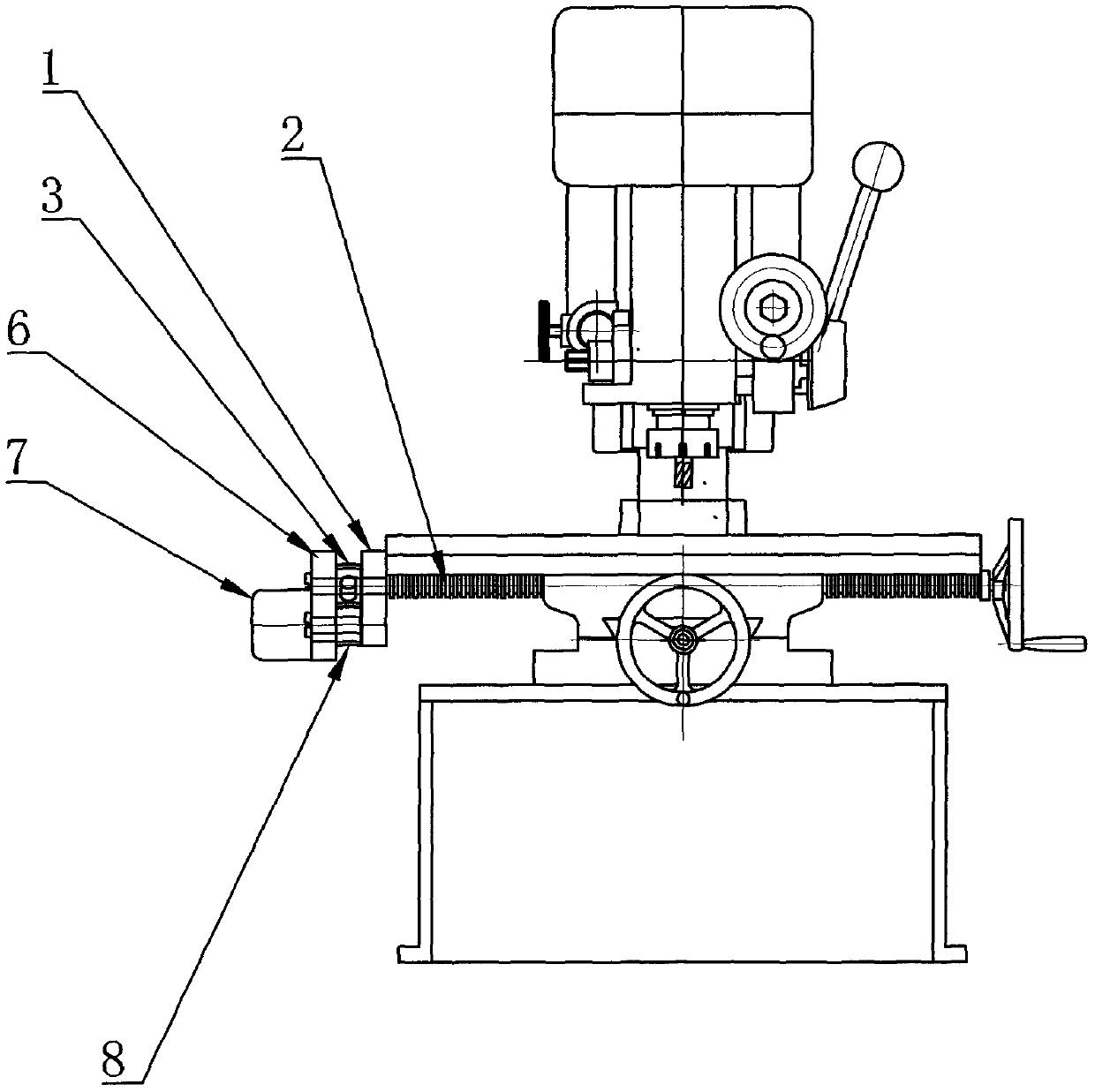
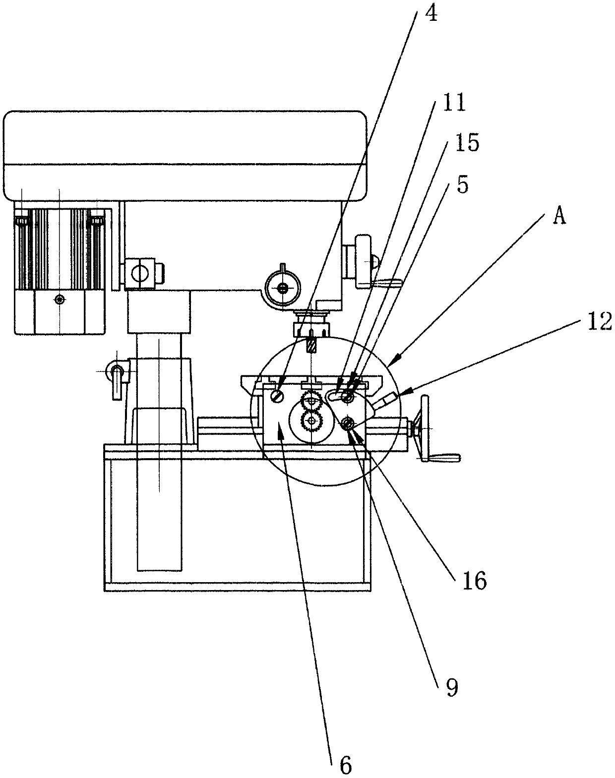
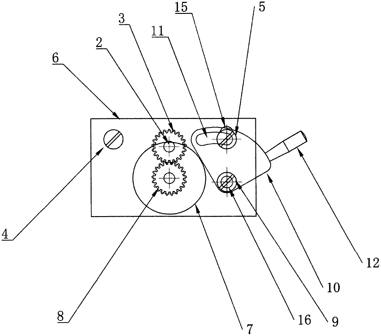
[0081] Depend on Figure 1 to Figure 7 As shown, the present embodiment is located at the automatic feeding mechanism and method of the micro-machine tool of the present invention. The gear 3 is combined; the driven screw 2 is threadedly connected with the machine tool, and the driven screw 2 pass...

Embodiment 2

[0086] Depend on Figure 8 to Figure 10 In another embodiment of the present invention shown, on the basis of Embodiment 1, the overall structure can be arranged on the machine tool.

Embodiment 3

[0088] Figure 11 to Figure 13 On the basis of Embodiment 1 and Embodiment 2, another embodiment of the fan-shaped plate 10 in the automatic feeding mechanism and method of the micro machine tool of the present invention is shown. In order to make the toggle adjustment of the fan-shaped plate 10 more stable, it is not necessary to will loosen, on the basis of Embodiments 1 and 2, the fan-shaped groove 11 of the original fan-shaped plate 10 is changed to include the first fan-shaped groove 19 and the second fan-shaped groove 20, the second fan-shaped groove 20 and the first fan-shaped groove 19 In the horizontal position, the second fan-shaped groove 20 is higher than the position of the first fan-shaped groove 19, and the radius of the second fan-shaped groove 20 is greater than the first fan-shaped groove 19, but the groove body of the first fan-shaped groove 19 and the second fan-shaped groove 20 The width is the same, and the first fan-shaped groove 19 and the second fan-sh...


PUM


Abstract

The invention relates to the field of machine tool machining and cutting, and more specifically relates to an automatic feeding mechanism and method for machining a miniature machine tool. The automatic feeding mechanism and method for the miniature machine tool aim at solving the problem that no effective and practical feeding mechanism is available on the market at present. The automatic feedingmechanism comprises a transition plate fixed on the miniature machine tool and a driven lead screw which is in threaded connection with the miniature machine tool and transversely penetrates throughthe transition plate, wherein the end part of the driven lead screw is provided with a driven gear, the transition plate is provided with a fixed hinge shaft and an upper hinge shaft, the transition plate is movably connected with a swing plate, the swing plate is provided with a fixed hinge shaft hole and a kidney-shaped groove hole, and the other side, which is opposite to the kidney-shaped groove hole, of the swing plate is provided with a lower hinge shaft. The automatic feeding mechanism further comprises a gear motor and the lower hinge shaft, wherein the output shaft end of the gear motor is provided with a driving gear located on the same plane with the driven gear, the lower hinge shaft is movably connected with a fan-shaped shifting block, the fan-shaped shifting block comprisesa lower hinge shaft hole and a fan-shaped groove, and the fan-shaped plate drives the swing plate through the fan-shaped groove to realize the engagement and disengagement of the driving gear and thedriven gear.

Description

Technical field: [0001] The invention relates to the field of machining and cutting of machine tools, and more specifically relates to an automatic feeding mechanism and method for micro machine tool machining. Background technique: [0002] Machine tools are generally suitable for parts processing. However, when traditional machine tools process parts, the precision is low, the efficiency is low, and there is no automatic feeding function. However, large-scale machine tools can be fed automatically, but they are expensive, complex in structure, numerous in parts, complex in operation, and bulky in size, so they are not practical for ordinary household use. But the small machine tool does not have good automatic feed mechanism at present; Feed amount work, at this time, the efficiency of the motor is extremely low, and the power consumption is very large. The constant torque output characteristic becomes worse, resulting in a smaller drive torque. In addition, the DC mot...

Claims


Application Information

Patent Timeline
IPC IPC(8): B23Q5/48
CPCB23Q5/48
Inventor 乔甡黄宁生曾卫民
Owner 江苏一首机械科技有限公司
Learn More