
Gas purifying and filling positive and negative pressure gas circuit switching device and using method thereof

A gas purification and switching device technology, which is applied to the installation device of container structure, container filling method, container discharge method, etc., can solve the problems of filling gas quality, long operation process, frostbite of operators, etc., and achieve remote control Monitoring and switching control, shortening the switching time, and improving the effect of environmental protection and safety

Pending Publication Date: 2020-03-24
MAINTENANCE BRANCH COMPANY STATE GRID ZHEJIANG ELECTRIC POWER +2
View PDF8 Cites 1 Cited by
  • Summary
  • Abstract
  • Description
  • Claims
  • Application Information

AI Technical Summary

Problems solved by technology

[0005] Third, because the traditional direct low-temperature liquid injection filling system has only one liquid injection pipe, and the processing device has a large processing capacity each time, it needs to fill multiple steel cylinders. When switching to fill steel cylinders, the liquid injection connection pipe needs Emission of partially vaporized SF6 gas;
[0006] Fourth, after the filling is completed, the remaining SF6 in the filling connection pipeline cannot be recovered, and the gas pressure will gradually increase, so it can only be discharged directly to the atmosphere;
[0007] Fifth, because SF6 is filled at low temperature, the filling connection pipe and the self-sealing joint of the cylinder are washed manually, and the operator has the risk of frostbite
At the same time, since the degree of scouring of filling pipes and cylinder self-sealing joints depends on the experience of the operator, it will have a certain impact on the quality of the filling gas
[0008] To sum up, the traditional SF6 purification filling equipment needs to discharge SF6 to the atmosphere in the process of filling and changing bottles in order to ensure that there is no air resistance and no air mixed in the original filling process. The operation process is long, wastes a lot of time, and there are hidden dangers to personal safety. The behavior of discharging SF6 into the atmosphere causes environmental pollution, and at the same time causes waste of SF6 gas source and complicated operation process.

Method used

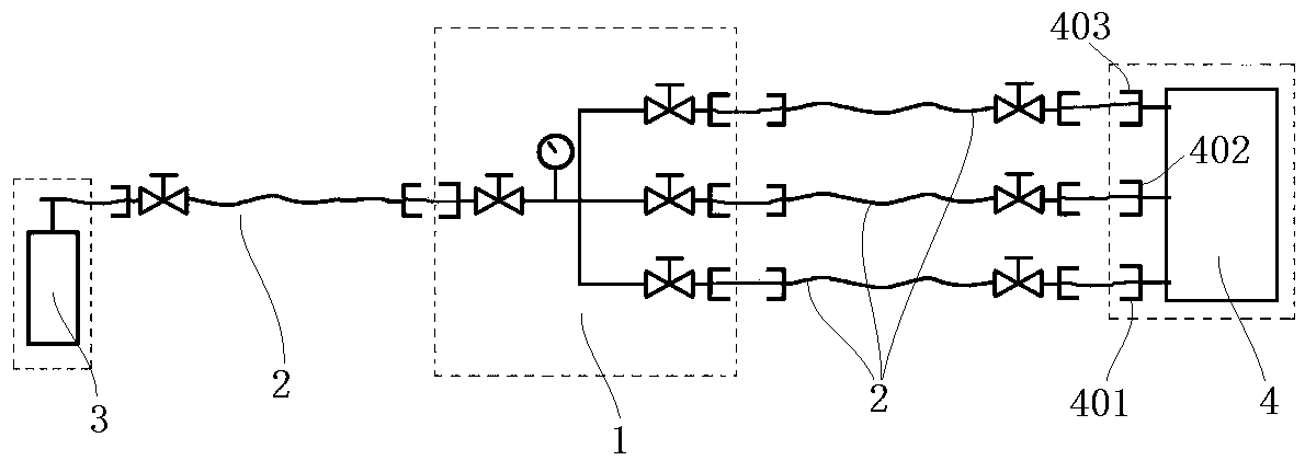

Image

  • Gas purifying and filling positive and negative pressure gas circuit switching device and using method thereof
  • Gas purifying and filling positive and negative pressure gas circuit switching device and using method thereof
  • Gas purifying and filling positive and negative pressure gas circuit switching device and using method thereof

Examples


example 1

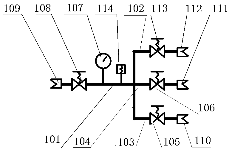
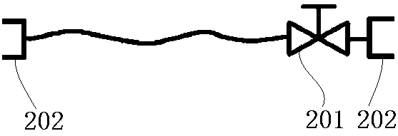
[0042] Such as Figure 1-3As shown, the positive and negative pressure gas path switching device for gas purification and filling includes a main gas path pipeline 101, a vacuum pressure gauge 107 is provided on the main gas path pipeline 101, and one end of the main gas path pipeline 101 is sequentially connected with a gas cylinder control valve 108 And the gas cylinder self-sealing joint 109, the gas cylinder self-sealing joint 109 is connected to the gas cylinder 3 through the detachable hose 2; the other end of the main gas pipeline 101 is provided with three branch pipelines, which are respectively a vacuum pipeline 102 and a recovery pipeline 104 And the filling pipeline 103, the vacuuming pipeline 102 is connected with a vacuuming control valve 113 and a vacuuming self-sealing joint 112, and the vacuuming self-sealing joint 112 is connected to the SF6 purification filling equipment 4 vacuuming port 403 through a detachable hose 2, and the recovery The pipeline 104 is c...

example 2

[0063] The difference from the above example is:

[0064] In order to realize remote switch control and simplify the switch operation, the gas cylinder control valve 108, the vacuum control valve 113, the recovery control valve 106, the filling control valve 105 and the hose valve 201 are all solenoid valves. Compared with mechanical valves, the control of solenoid valves is simpler, more convenient, and can be operated remotely.

[0065] In order to realize centralized control operation and improve operation safety, a pressure sensor 114 is also provided on the main gas pipeline 101 , and both the pressure sensor 114 and the solenoid valve are connected to the controller of the purification filling equipment 4 . By connecting the pressure sensor 114 and the solenoid valve to the controller of the purification filling equipment 4, the monitoring and operation can be concentrated at the position of the controller of the purification filling equipment 4, which can effectively re...


PUM


Abstract

The invention discloses a gas purifying and filling positive and negative pressure gas circuit switching device and a using method thereof, and relates to the technical field of gas purifying and filling. According to traditional SF6 purifying and filling equipment, SF6 needs to be discharged to the atmosphere during filling and bottle replacement, potential personal safety hazards exist, the environment is polluted, and meanwhile, gas sources and time are wasted. The device comprises a main gas path pipeline provided with a vacuum pressure gauge and a pressure sensor; one end of the main gaspath pipeline is provided with a control valve and a self-sealing joint, wherein the self-sealing joint is connected to a gas cylinder through a hose, and the other end is three branch pipelines, wherein the three-branch pipelines are respectively provided with an electromagnetic valve and a self-sealing joint; and the three branch pipelines are connected to a vacuumizing opening, a recycling opening and a filling opening of the purifying and filling equipment through hoses respectively. Through switching of the control valves on different channels, the whole filling work of gas cylinder vacuumizing, pipeline flushing, pressure relief and liquid filling is achieved; and the pipelines are not disassembled and assembled in the operation process, so that it is ensured that gas is not discharged to the atmosphere, automatic switching of gas paths is achieved, and the working efficiency and the environmental protection safety are improved.

Description

technical field [0001] The invention relates to the technical field of gas purification and filling, in particular to a positive and negative pressure gas circuit switching device for gas purification and filling and a use method thereof. Background technique [0002] At present, the traditional SF6 gas direct low-temperature liquid injection filling system has the following defects: [0003] First, before each filling connection to the first steel cylinder, in order to eliminate the air in the liquid injection connection pipe, the liquid injection connection pipe must discharge SF6 gas in advance; [0004] The second is to ensure that the residual air at the filling liquid connection pipe and the steel cylinder self-sealing joint does not enter the steel cylinder, the self-sealing joint of the steel cylinder must be flushed with SF6 gas, which leads to a certain amount of SF6 gas emission; [0005] Third, because the traditional direct low-temperature liquid injection fill...

Claims


Application Information

Patent Timeline
Patent Type & Authority Applications(China)
IPC IPC(8): F17C5/06F17C13/04F17C13/02F17C13/12
CPCF17C5/06F17C13/04F17C13/02F17C13/025F17C13/12F17C2205/0326F17C2205/0323F17C2221/01F17C2227/04F17C2250/043F17C2250/03F17C2260/04F17C2265/068
Inventor 戴鹏飞汪全虎郭全军陈韶辉董建新陈志鹏宋国海姚晖陈平陈晓锦邓华王坚俊范志远郦于杰刘威刘德仵蒙陈欣郑凯缪信成夏正权
Owner MAINTENANCE BRANCH COMPANY STATE GRID ZHEJIANG ELECTRIC POWER
Learn More