Bronchial spraying freezing system
A technology of spray freezing and bronchi, which is applied in the direction of catheters, cooling surgical instruments, medical science, etc., can solve the problems of risk, complicated balloon occlusion, cumbersome selection of balloon size, etc., and achieve the effect of simple and convenient operation
- Summary
- Abstract
- Description
- Claims
- Application Information
AI Technical Summary
Problems solved by technology
Method used
Image
Examples
Embodiment 1
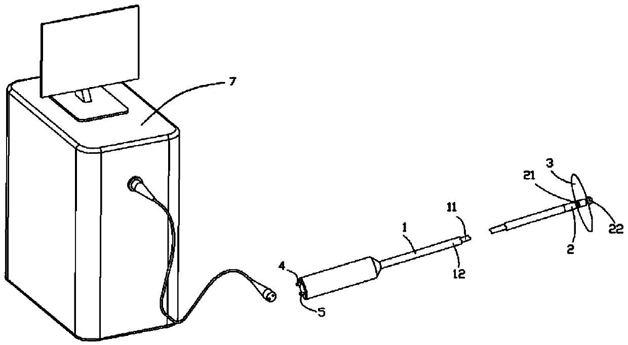
[0060] This embodiment combines the attached Figure 3-13 A preferred structure of the baffle plate 3 expanded by the cold source gas sprayed through the spray port 2 will be described.
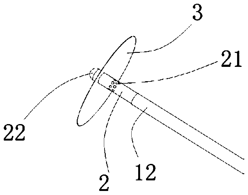
[0061] Depend on image 3 It can be seen that the spoiler 3 is located in the middle of the spray port 21 and the head end 22. When the spray port 21 is not sprayed with the cold source fluid, it is coated on the surface of the spray head 2. When the spray port 21 sprays the cold source, the cold source fluid is used. The power of the spoiler 3 is blown to the unfolded state.
[0062] 1. If Figure 4-Figure 7 As shown, the spoiler 3 is in the shape of an inner concave S shape, an outer concave S shape, an inner concave arc shape and an outer concave arc shape along the axial section of the vacuum tube. The baffle 3 is S-shaped or arc-shaped along the axial section of the vacuum tube. This shape can automatically adjust the degree of expansion at different sizes of plugs, so that the same b...
Embodiment 2
[0070] refer to Figure 18-Figure 20 , the present embodiment provides three preferred structures of the pushing device in the device pushing and unfolding mode.
[0071] 1. Reference Figure 18 The pushing device includes the outer sheath tube distal end 64, and the outer sheath tube distal end 64 includes a cutout 641 and a head end 642, and the spray port 21 is inside the cutout 641, which will not block the spraying of the cold source. The baffle 3 is directly pushed away with the head end 642 of the outer sheath to realize its expansion, and the baffle 3 will also be brought back when the outer sheath is recovered.
[0072] 2. Reference Figure 19 , the pushing device includes an outer sheath distal end 64 and a support device 31 , the support device includes but not limited to a support rod and a support wire, and the outer sheath distal end 64 is connected to the baffle 3 through the support device 31 . Through the joint action of the distal end 642 of the outer shea...
Embodiment 3
[0075] This embodiment provides a preferred structure in which the outer sheath exists at the distal end of the outer sheath in embodiment 2.
[0076] 1. Reference Figure 21 and Figure 22 , the outer sheath 6 also includes a connection bayonet 63 , and the body 61 of the outer sheath is connected to the distal end 64 of the outer sheath through the connection buckle 63 . The setting of the connection bayonet 63 can realize the detachment of the outer sheath.
[0077] 2. Reference Figure 23 and Figure 24 , the body 61 of the outer sheath tube and the distal end 64 of the outer sheath tube are integrated, and there is no connecting buckle in the middle.
[0078] To sum up, the spoiler is deployed through the push device, and the deployment process is easier to control. The distal end of the outer sheath is provided with an incision corresponding to the nozzle, which will not affect the spray effect. There are reinforcing wires on the spoiler, so that the spoiler has a ...
PUM
 Abstract
Description
Claims
Application Information
 - R&D
- Intellectual Property
- Life Sciences
- Materials
- Tech Scout
- Unparalleled Data Quality
- Higher Quality Content
- 60% Fewer Hallucinations
Browse by: Latest US Patents, China's latest patents, Technical Efficacy Thesaurus, Application Domain, Technology Topic, Popular Technical Reports.
© 2025 PatSnap. All rights reserved.Legal|Privacy policy|Modern Slavery Act Transparency Statement|Sitemap|About US| Contact US: help@patsnap.com


