Transformer substation intelligent drainage system and method
A technology for intelligent drainage and substations, applied in waterway systems, sewage removal, drainage structures, etc., can solve problems such as poor drainage effect and poor detection effect.
- Summary
- Abstract
- Description
- Claims
- Application Information
AI Technical Summary
Problems solved by technology
Method used
Image
Examples
Embodiment 1
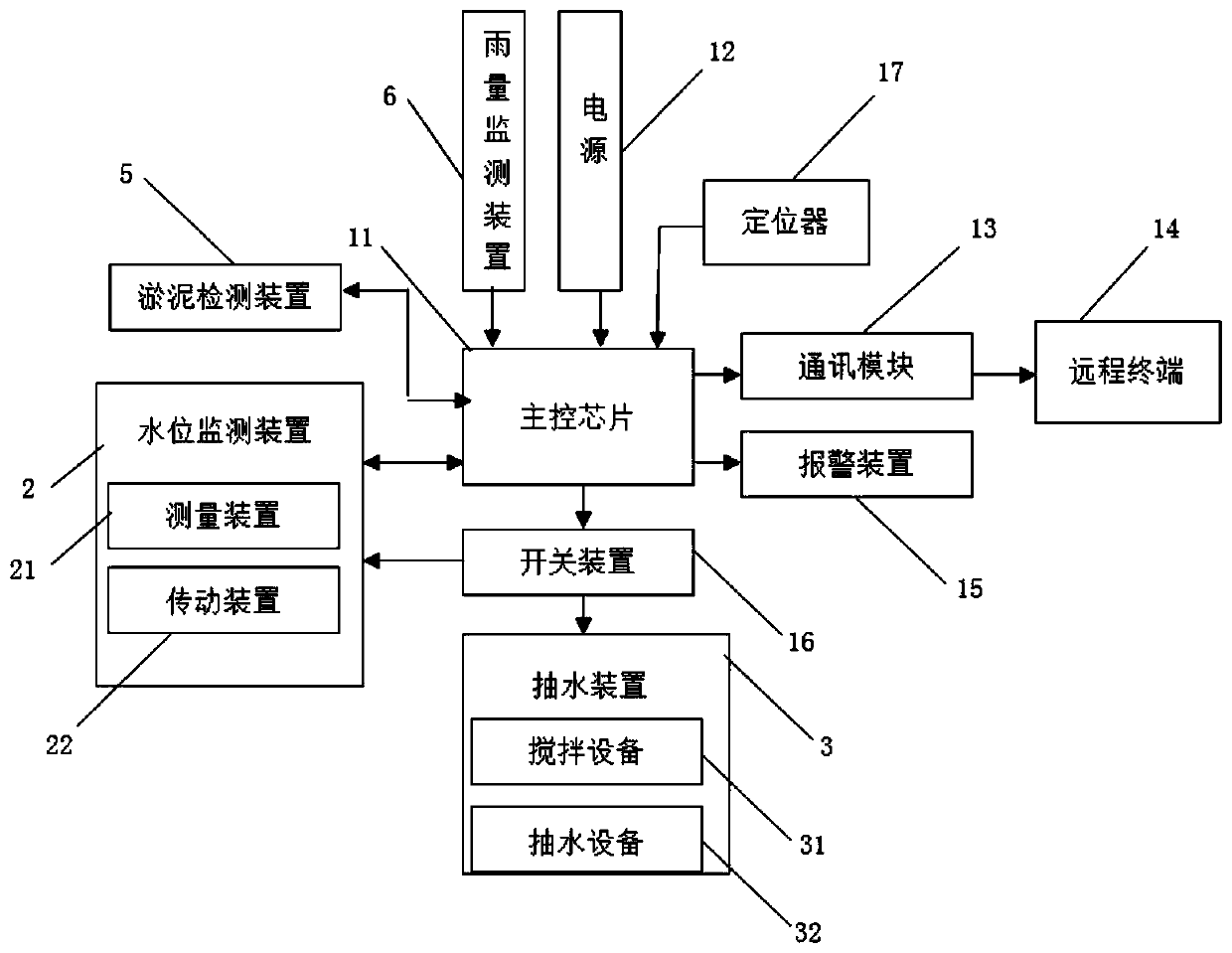
[0075] Such as figure 1 As shown, a substation intelligent drainage system is composed of a pumping device 3, a water level monitoring device 12, a silt detection device 5, a rainfall monitoring device 6, and a controller 1, the pumping device 3, a water level monitoring device 12, a silt detection device 5, and a rainfall monitoring device The devices 6 are electrically connected to the controller 1 respectively. The controller 1 is composed of a main control chip 11, a power supply 12, a communication module 13, an alarm device 15, a locator 17 and a switch device 16. The power supply 12 is electrically connected to the controller 1. The main control The chip 11 is electrically connected to the alarm device 15 , the communication module 13 , the locator 17 and the switch device 16 respectively.
[0076]In the present embodiment, communication module 13 adopts GTM900-C GPRS communication module 13, the stability of data transmission based on GTM900-C GPRS communication module...
Embodiment 2
[0093] Embodiment 2 is the improvement to water pump on the basis of embodiment 1, as Figure 8 Shown is the installation structure diagram of the water pump, and the water pump of embodiment 2 is installed at the bottom of the sump well.
[0094] Such as Figure 9 , Figure 10 As shown, the water pump 321 includes a support ring 503-water outlet 504-motor 501 and water pump blades 505. The lower part of the support ring 503 is in the shape of an inverted bell mouth. The lower part of the support ring 503 has a strip-shaped water inlet gap along the circumference. It is a collection part 502 in a cylindrical tubular shape. The water outlet 504 is installed in the middle of the support ring 503 and communicates with the collection part 502. The motor 501 is fixedly installed on the top of the support ring 503. The top of the support ring 503 has an end cover. The output shaft of the motor 501 extends into The lower part of the support ring 503, the water pump blade 505 is fix...
Embodiment 3
[0100] This embodiment has been further improved on the basis of Embodiment 1, such as Figure 13 As shown, the water belt 511 in this embodiment also includes a water inlet head 512, the water belt 511 is a hollow cuboid, the free end of the water belt 511 is closed, and there are several gaps on both sides of the water belt 511. The water head 512; the water inlet head 512 includes a shell and a floating block 5122, the two ends of the shell are open, one end of the shell is connected to the gap, and the other end of the shell is processed with a slot 5121 for clamping the floating block 5122 along the plumb direction , the floating block 5122 is movably engaged in the slot 5121 along the vertical direction, and the floating block 5122 covers the opening area. When there is accumulated water at the water inlet head 512, the accumulated water has a buoyancy effect on the floating block 5122, thereby opening the water inlet head 512, so that the water body can enter the hose 5...
PUM
 Abstract
Description
Claims
Application Information
 - R&D
- Intellectual Property
- Life Sciences
- Materials
- Tech Scout
- Unparalleled Data Quality
- Higher Quality Content
- 60% Fewer Hallucinations
Browse by: Latest US Patents, China's latest patents, Technical Efficacy Thesaurus, Application Domain, Technology Topic, Popular Technical Reports.
© 2025 PatSnap. All rights reserved.Legal|Privacy policy|Modern Slavery Act Transparency Statement|Sitemap|About US| Contact US: help@patsnap.com


