
A substation intelligent drainage system and method thereof

A technology of intelligent drainage and substation, which is applied in the direction of waterway system, sewage drainage, drainage structures, etc., and can solve the problems of poor detection effect and poor drainage effect

Active Publication Date: 2021-02-26
JIAXING HENGCHUANG ELECTRIC POWER DESIGN & RES INST CO LTD +1
View PDF2 Cites 0 Cited by
  • Summary
  • Abstract
  • Description
  • Claims
  • Application Information

AI Technical Summary

Problems solved by technology

[0010] The purpose of the present invention is to solve the problem of poor drainage effect and poor detection effect of the existing cable trench drainage device, and design a substation intelligent drainage system and its method. The protection device and the stirring device for removing sludge ensure the accuracy of water level gauge measurement and the pumping efficiency of the pumping device

Method used


Image

  • A substation intelligent drainage system and method thereof
  • A substation intelligent drainage system and method thereof
  • A substation intelligent drainage system and method thereof

Examples


Embodiment 1

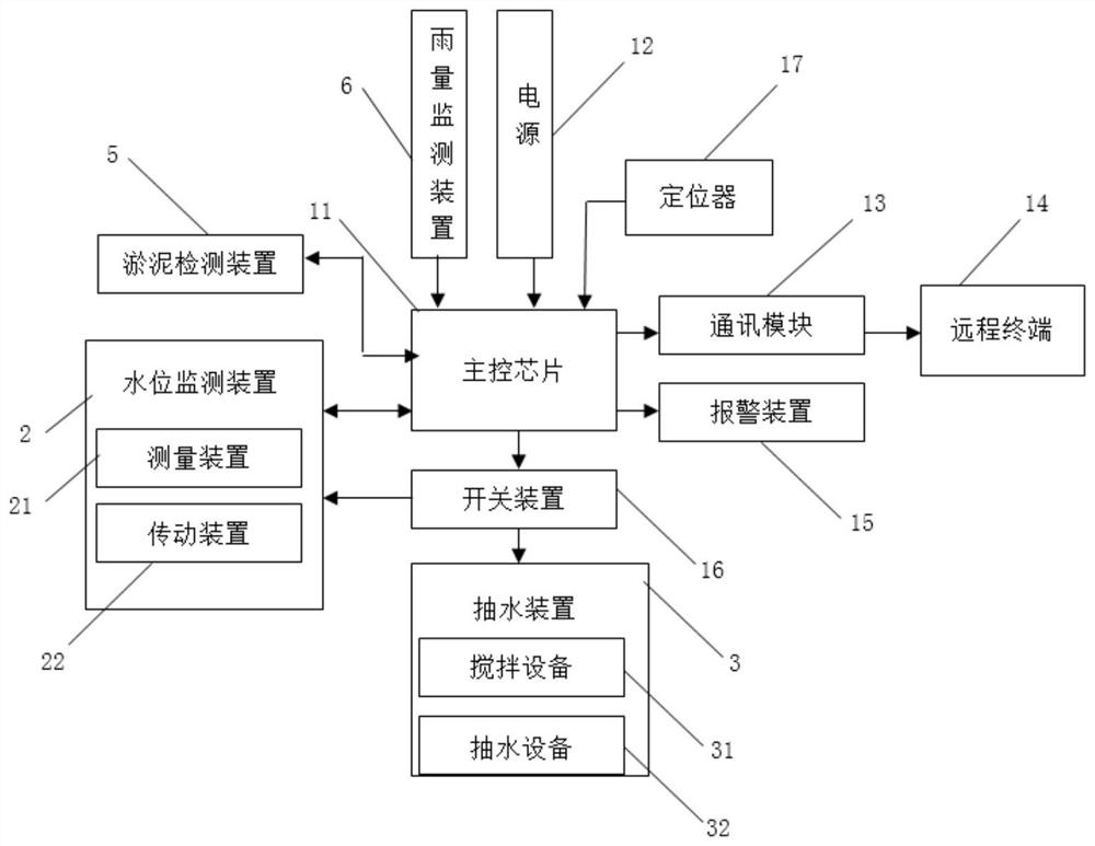
[0075] Such as figure 1 As shown, a substation intelligent drainage system is composed of a pumping device 3, a water level monitoring device 12, a silt detection device 5, a rainfall monitoring device 6 and a controller 1, the pumping device 3, a water level monitoring device 12, a silt detection device 5, and a rainfall monitoring device The devices 6 are respectively electrically connected to the controller 1, the controller 1 is composed of a main control chip 11, a power supply 12, a communication module 13, an alarm device 15, a locator 17 and a switch device 16, the power supply 12 is electrically connected to the controller 1, and the main control The chip 11 is electrically connected to the alarm device 15 , the communication module 13 , the locator 17 and the switch device 16 respectively.

[0076]In the present embodiment, communication module 13 adopts GTM900-C GPRS communication module 13, the stability of data transmission based on GTM900-C GPRS communication mod...

Embodiment 2

[0093] Embodiment 2 is the improvement to water pump on the basis of embodiment 1, as Figure 8 Shown is the installation structure diagram of the water pump, and the water pump of embodiment 2 is installed at the bottom of the sump well.

[0094] Such as Figure 9 , Figure 10 As shown, the water pump 321 includes a support ring 503-water outlet 504-motor 501 and water pump blades 505. The lower part of the support ring 503 is in the shape of an inverted bell mouth. The lower part of the support ring 503 has a strip-shaped water inlet gap along the circumference. It is a collection part 502 in a cylindrical tubular shape. The water outlet 504 is installed in the middle of the support ring 503 and communicates with the collection part 502. The motor 501 is fixedly installed on the top of the support ring 503. The top of the support ring 503 has an end cover. The output shaft of the motor 501 extends into The lower part of the support ring 503, the water pump blade 505 is fix...

Embodiment 3

[0100] This embodiment has been further improved on the basis of Embodiment 1, such as Figure 13 As shown, the water belt 511 in this embodiment also includes a water inlet head 512, the water belt 511 is a hollow cuboid, the free end of the water belt 511 is closed, and there are several gaps on both sides of the water belt 511. The water head 512; the water inlet head 512 includes a shell and a floating block 5122, the two ends of the shell are open, one end of the shell is connected to the gap, and the other end of the shell is processed with a slot 5121 for clamping the floating block 5122 along the plumb direction , the floating block 5122 is movably engaged in the slot 5121 along the vertical direction, and the floating block 5122 covers the opening area. When there is accumulated water at the water inlet head 512, the accumulated water has a buoyancy effect on the floating block 5122, thereby opening the water inlet head 512, so that the water body can enter the hose 5...


PUM


Abstract

The invention discloses a substation intelligent drainage system and a method thereof, comprising a pumping device installed in a cable trench, a water level monitoring device, a sludge detection device, a rainfall monitoring device and a controller; the pumping device is used to draw out the cable trench The accumulated water in the cable trench is electrically connected to the controller; the water level monitoring device is used to monitor the accumulated water in the cable trench and is electrically connected to the controller; the controller is used to process the feedback information of the water level detection device and control the The start and stop of the pumping device is connected to the remote terminal by communication; the rainfall monitoring device is used to monitor the environmental rainfall and is electrically connected to the controller; electrical connection. Considering the silt accumulation in the cable trench, the device is equipped with a vibrating device, a transmission device and a stirring device to ensure the measurement accuracy of the water level gauge and the pumping efficiency of the pumping device.

Description

technical field [0001] The invention relates to the technical field of power equipment protection, in particular to a substation intelligent drainage system and a method thereof. Background technique [0002] Cable trench is an underground pipeline used to place and protect cable facilities, and is an indispensable infrastructure in power plants-substations-municipal engineering and large factories and mines. However, due to terrain or design factors, it is easy to accumulate water in the cable trench during heavy rain or rainy season. If the water level is too high, the cables in the cable trench will be soaked in water for a long time and corroded, which will not only damage the insulation of the cable, but also affect its In severe cases, it will also cause bursting due to water ingress in the cable. [0003] The drainage speed of the existing cable trench drainage system is slow. After the rain, staff need to go to the site to inspect and realize manual drainage, which ...

Claims


Application Information

Patent Timeline
Patent Type & Authority Patents(China)
IPC IPC(8): E03F1/00E03F5/22E03F5/04E03F5/26G01W1/00G01F23/14G01B7/06
CPCE03F1/00E03F5/04E03F5/22E03F5/26E03F2201/20E03F2201/30G01B7/10G01F23/14G01W1/00
Inventor 洪晓燕路瑶柯杰周刚李冲卢亚军张立峰杨帆卫波杨晓军
Owner JIAXING HENGCHUANG ELECTRIC POWER DESIGN & RES INST CO LTD
Learn More