Adjustable flue gas uniform distribution device for submerged combustion gasifier

A submerged combustion and adjustable technology, applied in the field of LNG vaporizers, can solve the problem of serious icing in the "dead zone" that cannot be adjusted for the injection speed, and achieve the effects of saving energy consumption, facilitating maintenance, and avoiding the formation of ice layers

Active Publication Date: 2020-03-27
XI'AN PETROLEUM UNIVERSITY
View PDF7 Cites 2 Cited by
  • Summary
  • Abstract
  • Description
  • Claims
  • Application Information

AI Technical Summary

Problems solved by technology

[0004] In order to overcome the problems that the existing SCV smoke spray uniform distributor cannot adjust the spray speed and the "dead zone" freezes seriously in the operation of the existing SCV smoke spray uniform distributor, the present invention proposes an adjustable The type flue gas uniform distribution device adopts an adjustable flue gas uniform device, and adjusts the effective injection area of ​​the spray hole of the uniform device according to the flue gas volume, so that the flue gas injection speed and the required flue gas volume of the LNG heat transfer tube can be obtained. Matching, that is, on the one hand, adjust the flue gas injection speed, effectively

Method used


Image

  • Adjustable flue gas uniform distribution device for submerged combustion gasifier
  • Adjustable flue gas uniform distribution device for submerged combustion gasifier
  • Adjustable flue gas uniform distribution device for submerged combustion gasifier

Examples


Embodiment Construction

[0024] The present invention is described in detail below in conjunction with accompanying drawing.

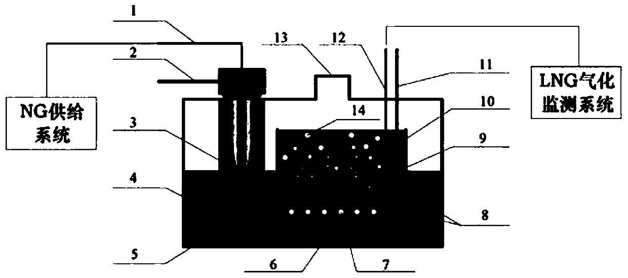
[0025] figure 1 It is an adjustable flue gas uniform distribution device commonly used in submerged combustion gasifiers in the prior art. NG passes through NG inlet 1, air 2 passes through air inlet 2 and is mixed and burned in combustion chamber 3, and the combustion chamber 3 is immersed in the water bath 4, and the generated flue gas of the combustion product is used as a heat source for LNG gasification heating. The flue gas enters the flue gas distributor 6 along with the flue gas pipe 5 , the flue gas homogenizer 6 is located below the cofferdam 9 , and the heat transfer tube bundle 10 is arranged in the cofferdam 9 in a direction perpendicular to the flue gas pipe 5 . The flue gas is sprayed into the water bath 4 in the form of bubbles 14 through the flue gas injection holes 7, causing the water bath 4 to generate "pseudo-static" turbulence and traverse the heat trans...


PUM


Abstract

The invention discloses an adjustable flue gas uniform distribution device for an submerged combustion gasifier. The adjustable flue gas uniform distribution device comprises a flue gas uniform distributor, wherein the flue gas uniform distributor is composed of an inner flue gas uniform distributor pipe section, an outer flue gas uniform distributor pipe section and a dead zone turbulent flow section; two ends of the inner flue gas uniform distributor pipe section are connected with the dead zone turbulent flow section, one end of the inner flue gas uniform distributor pipe section is in a flange connection mode, and the other end of the inner flue gas uniform distributor pipe section is in a welding mode; and the inner flue gas uniform distributor pipe section is coaxially embedded intothe outer flue gas uniform distributor pipe section, and the outer flue gas uniform distributor pipe section is connected with the power output of an electric servo system actuating mechanism. According to the requirement of the gasification rate and the gasification amount, the electric servo system actuating mechanism A drives the outer flue gas uniform distributor pipe section to rotate to a corresponding angle to change the diameter of a flue gas spraying hole so as to adjust the effective flue gas spraying area, and therefore, the spraying speed of the flue gas is controlled in a certainrange, so that the flue gas fully exchanges heat with a water bath, the disturbance of a strong transverse pipe bundle is achieved, the freezing of a serpentine coil pipe is avoided, and the purpose of improving the gasification rate is achieved.

Description

technical field [0001] The invention belongs to the technical field of LNG gasifiers, in particular to an adjustable flue gas uniform distribution device for submerged combustion gasifiers. Background technique [0002] Submerged combustion vaporizer (Submerged Combustion Vaporizer, referred to as SCV) is a multi-phase flow heat exchange technology developed on the basis of submerged combustion technology. low-level features. Due to seasonal fluctuations in natural gas demand, which is 2-3 times the normal amount in winter, SCVs are often used as special peak-shaving equipment for natural gas systems at receiving stations. SCVs used in domestic natural gas receiving stations are mainly imported from Japan, Germany and South Korea. The document "Application Publication No. US7168395B2 American Invention Patent" discloses that the main structure of this submerged combustion gasifier consists of heat exchange tube bundles, shell-side cofferdams and water baths, submerged burn...

Claims


Application Information

Patent Timeline
IPC IPC(8): F22B1/18F22B1/26F23C3/00
CPCF22B1/1853F22B1/265F23C3/004
Inventor 白俊华潘杰李冉何晓茹王凯吴刚杨睿杰
Owner XI'AN PETROLEUM UNIVERSITY
Why Eureka
Try Eureka