Micro-grid system

A technology of micro grid and photovoltaic power generation system, applied in the field of power grid, can solve the problems of high cost of SMES, low energy storage density of a single capacitor, and expensive counterfeiting.

Pending Publication Date: 2020-03-27
GANZHOU TIANMU PILOT TECH
View PDF0 Cites 4 Cited by
  • Summary
  • Abstract
  • Description
  • Claims
  • Application Information

AI Technical Summary

Problems solved by technology

Studies have shown that the superconducting magnetic energy storage technology SMES is very suitable for power system stability control, but SMES is expensive, device design, operation and maintenance are very different from the existing various radiation equipment in the power system, and its long-term Safe and stable operation is being explored, and supercapacitor energy storage technology has not yet reached the experimental stage due to the cost of counterfeiting and low energy storage density of a single capacitor

Method used


Image

  • Micro-grid system
  • Micro-grid system
  • Micro-grid system

Examples


Embodiment Construction

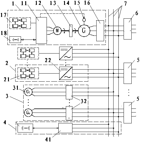
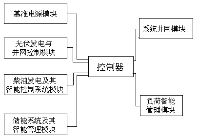
[0044] figure 1 A micro-grid system, the whole system can be divided into six modules according to their functions, namely, the reference power supply module 1, the photovoltaic power generation and grid-connected control module 2, the diesel generator and its intelligent control system module 3, the energy storage system and its Intelligent management module 4, load intelligent management module 5, system grid connection module 6.

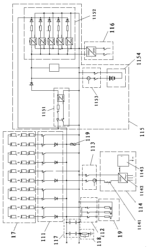
[0045] The reference power module includes photovoltaic array A17, CCS intelligent control center 11, motor 12, flywheel 13, AC synchronous generator 14, photovoltaic array A17 is connected to CCS intelligent control center 11, CCS intelligent control center 11 is connected to motor 12, and motor 12 outputs The shaft is connected to the flywheel 13, and the other end of the flywheel 13 shaft is connected to the AC synchronous generator 14, and the synchronous generator 14 is incorporated into the AC bus 7 through the grid-connected inverter;

[0...


PUM


Abstract

The invention discloses a micro-grid system, and relates to a power grid technology, in particular to a micro-grid system. A micro-grid low-voltage power supply bus is connected in parallel through agrid-connected inverter, boosted to 10KV through a power supply transformer, and connected in a state grid. The microgrid system not only can realize stable power supply in the grid, but also can be stably butted with a large power grid system. The system comprises a photovoltaic power generation system, a diesel generator system and a battery energy storage system, wherein the photovoltaic powergeneration system and the diesel generator system are used as distributed power supplies; the whole microgrid system is divided into six modules. The system comprises a reference power supply module,a photovoltaic power generation and grid-connected control module, a diesel generator and an intelligent control system module thereof, an energy storage system and an intelligent management module thereof, a load intelligent management module and a system grid-connected module. As a complete power system, functions of power balance control, system operation optimization, fault detection and protection, electric energy quality management and the like are realized by means of self-control and management energy supply.

Description

technical field [0001] The invention relates to a grid technology, in particular to a micro grid system. Background technique [0002] Power balance is the basis for the stable operation of the power system. Once the power is seriously unbalanced due to a fault, the system may lose stability and cause a large-scale power outage, which will cause major economic losses and serious social impact. In order to solve this problem, the traditional method It uses relay protection and safety and stability control devices to perform operations such as machine cut-off, load cut-off, or system de-loading when the system fails, so as to alleviate the power imbalance problem caused by the fault in the system as much as possible. This kind of stability control measure is called Passive stabilization, if there is such a device, it can feel the unbalanced power of the system in real time online, and directly compensate and adjust it, so as to solve the problem of power system stability cause...

Claims


Application Information

Patent Timeline
Patent Type & Authority Applications(China)
IPC IPC(8): H02J3/38H02J3/32H02J3/30H02J3/24
CPCH02J3/24H02J3/30H02J3/32H02J3/381Y02E10/56Y02E60/16Y02E70/30
Inventor 吕小平谢菊梅罗建明夏阳开熊显应刘业胜
Owner GANZHOU TIANMU PILOT TECH
Why Eureka
Try Eureka