Horizontal connecting structure for assembled wall

A connection structure and assembly technology, applied in the direction of walls, building components, building structures, etc., can solve the problems of poor stability and difficult splicing, and achieve the effect of reducing the use of bolts, facilitating splicing, and simplifying the construction process

Pending Publication Date: 2020-03-31
西南科技大学城市学院
View PDF1 Cites 1 Cited by
  • Summary
  • Abstract
  • Description
  • Claims
  • Application Information

AI Technical Summary

Problems solved by technology

[0004] In order to solve the technical problems of poor stability and difficult splicing between shear walls in the prior art, the present invention provides a horizontal connection structure for assembled walls

Method used


Image

  • Horizontal connecting structure for assembled wall
  • Horizontal connecting structure for assembled wall
  • Horizontal connecting structure for assembled wall

Examples


Embodiment 1

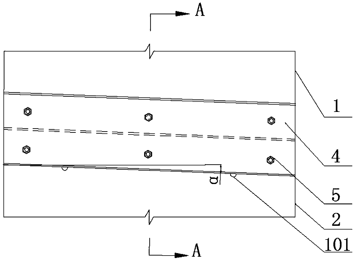
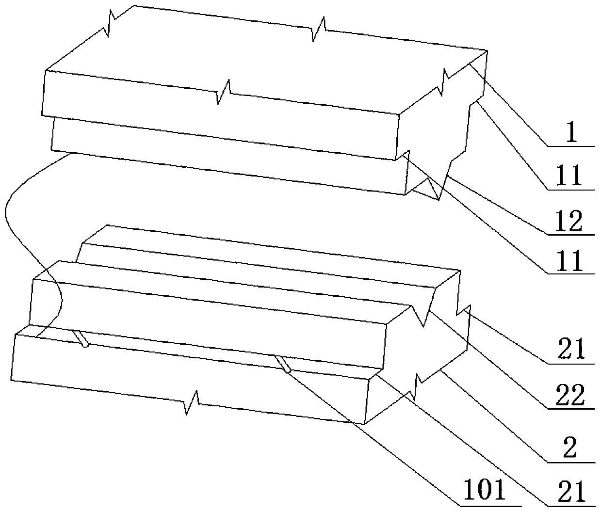
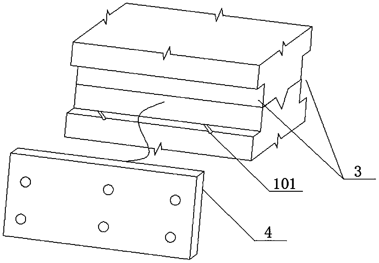
[0030] Such as figure 1 , figure 2 , image 3 and Figure 4 As shown, the horizontal connection structure for the assembled wall of the present invention includes a wall, and the wall includes a first wall 1 and a second wall 2 connected to each other in the vertical direction, and the first wall 1 First steps 11 are provided on both sides of the second wall 2, and second steps 21 are provided on both sides of the second wall 2, and the first steps 11 and the second steps 21 are enclosed to form a through groove 3; The connecting piece 4 inside the slot 3 and matched with the slot 3 is a metal plate structure; the connecting piece 4 is connected to the first wall 1 and the second wall 2 through bolts 5 respectively. The bolts 5 sequentially pass through the first step on one side, the wall and the first step on the other side to connect with the nuts 6 . The first step 11 is provided with a drainage groove 101 ; the bottom of the through groove 3 is provided with a waterp...

Embodiment 2

[0033] This embodiment is a further improvement made on the basis of the first embodiment. Such as figure 2 , image 3 and Figure 4 As shown, the side of the first wall 1 connected to the second wall 2 is provided with a protruding post 12 , and the second wall 2 is provided with a slide groove 22 matching the protruding post 12 at a corresponding position.

[0034] Working principle: The structure of the convex column plays a certain role in waterproofing, preventing water from entering the joint of the wall; When splicing between walls, the convex column can slide in the chute, so as to avoid misalignment between walls.

Embodiment 3

[0036] This embodiment is a further improvement made on the basis of the second embodiment. Such as figure 2 , image 3 and Figure 4 As shown, the slide groove 22 is a tapered groove, and the width of the tapered groove gradually decreases in the direction away from the first wall 1 .

[0037] Working principle: Since the tapered groove is wide at the top and narrow at the bottom, when splicing between the walls, the tapered groove first limits the position of the convex column to avoid misalignment and horizontal rotation between the walls; Therefore, the tapered groove has a guiding effect on the convex post, and the convex post is automatically aligned with the tapered groove, thereby increasing the speed of splicing between walls.


PUM


Abstract

The invention discloses a horizontal connecting structure for an assembled wall. The horizontal connecting structure comprises the wall. The wall comprises a first wall and a second wall connected toeach other in a vertical direction. A first step is arranged on the first wall, a second step is arranged on the second wall, and the first step and the second step encircle a straight slot. The horizontal connecting structure also comprises a connecting part arranged in the straight slot and matched with the straight slot. The connecting part is of a plate structure. The connecting part is connected to the first wall and the second wall through bolts, separately. Compared with a splicing mode in the prior art, the adjacent two walls in the two vertical directions are connected by means of theconnecting part of the plate structure, and the connecting area of the two spliced walls is increased, so that the spliced wall is steadier, meanwhile, use of bolts is also reduced, the constructionsteps are simplified, the construction difficulty is reduced, the construction efficiency is improved and the construction cost is lowered.

Description

technical field [0001] The invention relates to the technical field of building construction, in particular to a horizontal connection structure for an assembled wall. Background technique [0002] With the development of modern industrial technology, prefabricated buildings have begun to arouse people's interest. The prefabricated building refers to the transfer of a large number of on-site operations in the traditional construction method to the factory, where the building components and accessories are processed and manufactured, transported to the construction site, and assembled and installed on site through reliable connection methods. . Prefabricated buildings mainly include prefabricated concrete structures, steel structures, modern wooden structures, etc., because of the use of standardized design, factory production, assembly construction, information management, and intelligent applications, they are representatives of modern industrial production methods. The p...

Claims


Application Information

Patent Timeline
Patent Type & Authority Applications(China)
IPC IPC(8): E04B2/00E04B1/38
CPCE04B2/00E04B1/38E04B1/388
Inventor 李超周海波王梓龙张玉苹
Owner 西南科技大学城市学院
Why Eureka
Try Eureka