Optical fiber ring type residual stress test system and residual stress test method

A residual stress and testing system technology, which is applied in the direction of force measurement, measurement force, and measurement device by measuring the change of optical properties of materials when they are stressed, which can solve the problem of increasing the difficulty and complexity of the drilling method, and the inability to penetrate the material. The overall stress distribution test, inconvenient wiring of multiple resistance strain gauges, etc., can reduce the difficulty of connection, simple structure, and reduce errors.

Active Publication Date: 2020-03-31
INST OF CHEM MATERIAL CHINA ACADEMY OF ENG PHYSICS +1
View PDF9 Cites 3 Cited by
  • Summary
  • Abstract
  • Description
  • Claims
  • Application Information

AI Technical Summary

Problems solved by technology

Its disadvantage is that it is easy to tilt the angle during the actual patch, so that the axis of the strain gauge is not on the radius with the center of the drilled hole as the center, which causes a large error between the test results and the actual results. After the method test is completed, if you want to improve the accuracy, you must measure the actual patch deviation angle of the strain gauge and then bring it into the formula to correct this deviation for conversion.
On the one hand, this increases the difficulty and complexity of the drilling process, on the other hand, it also reduces the test accuracy
Secondly, if multiple sensors are placed to verify the test results, it is inconvenient to connect multiple resistance strain gauges, and the number that can be placed is limited by the size of the sensors, so it is impossible to test the overall distribution of internal stress in the material

Method used


Image

  • Optical fiber ring type residual stress test system and residual stress test method
  • Optical fiber ring type residual stress test system and residual stress test method
  • Optical fiber ring type residual stress test system and residual stress test method

Examples


Embodiment 1

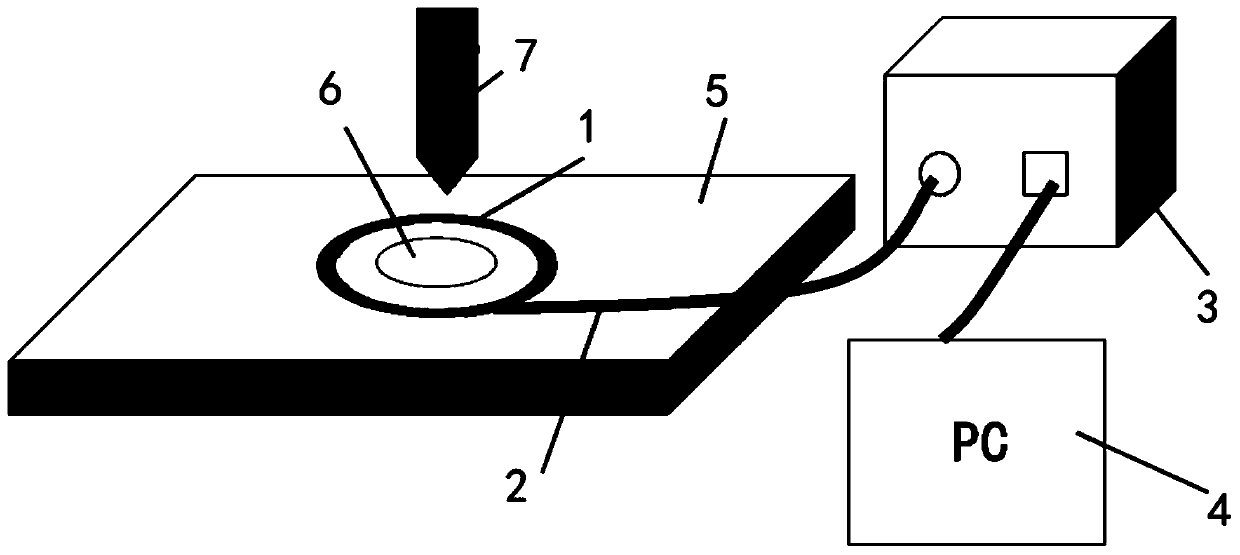
[0055] Such as figure 1 As shown, an optical fiber ring type residual stress testing system includes several optical fiber sensors, transmission optical fiber 2, demodulation device 3 and data processing device 4.

[0056] A number of optical fiber sensors are connected in series through the transmission optical fiber 2 and wound into a circle to form the optical fiber sensor ring 1. It can be realized by marking or making circular grooves of the same size. The optical fiber sensor ring 1 is fixed on the surface of the material 5 to be tested and connected to the demodulation device 3 through the transmission fiber 2 , and the demodulation device 3 is electrically connected with the data processing device 4 .

[0057] The fiber optic sensor is used to test the wavelength signal of the measuring point before and after drilling, and transmits the measured wavelength signal to the demodulation device 3 through the transmission fiber 2, and the demodulation device 3 is used to de...

Embodiment 2

[0066] This embodiment discloses a method for residual stress testing using the optical fiber ring type residual stress testing system of Embodiment 1, which specifically includes the following steps:

[0067] Step 1. Mark the center of the drilling hole at the center of the surface of the material 5 to be tested, and use this mark as the center of the fiber sensor ring 1 to set the installation position of the fiber sensor ring 1;

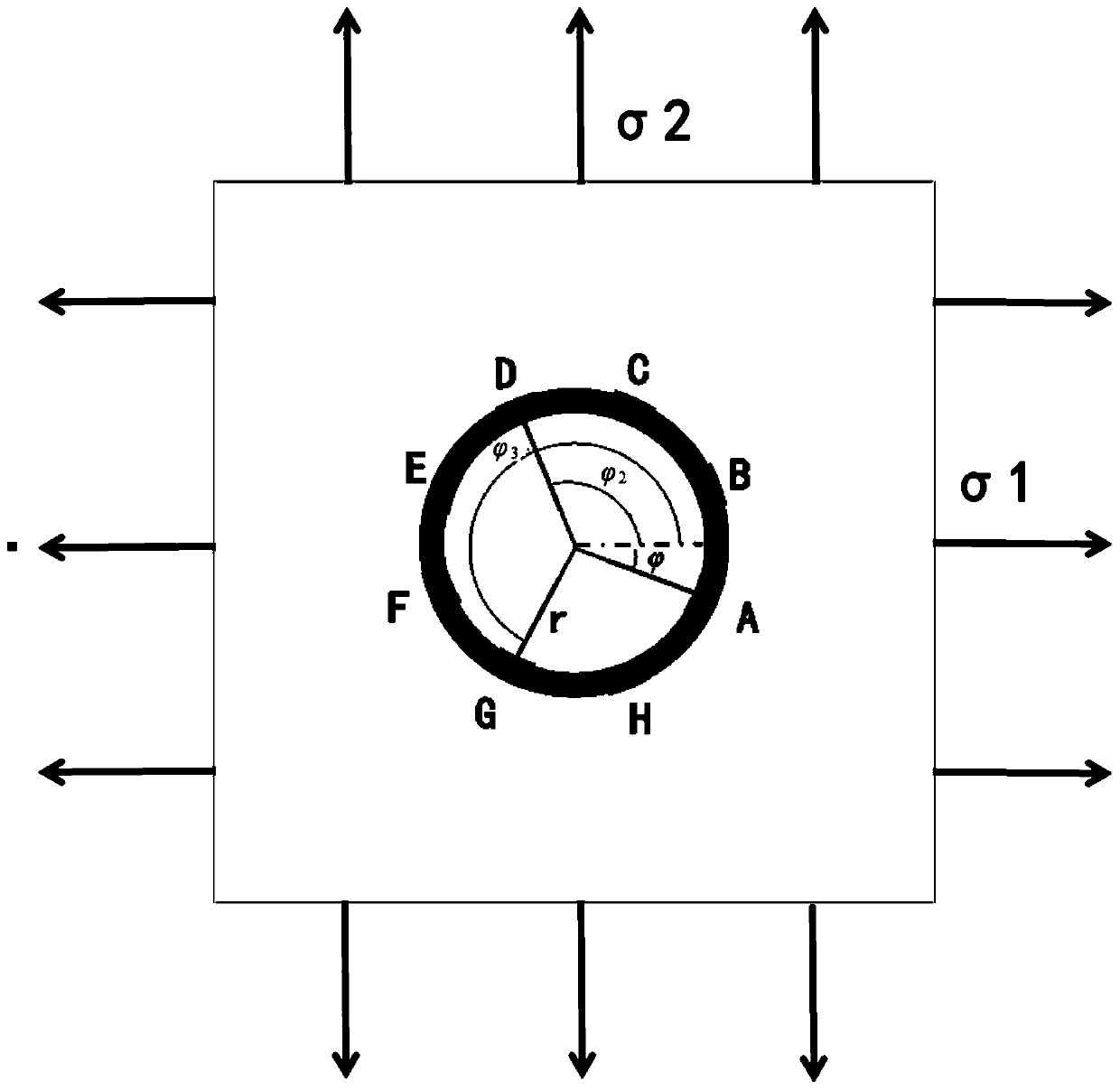
[0068] Step 2. Put 8 fiber optic sensors (such as image 3 The optical fiber sensors A, B, C, D, E, F, G, H) are connected in series through the transmission optical fiber 2 and wound into a circle to form an optical fiber sensor ring 1; location;

[0069] Step 3. Complete the connection between the optical fiber sensor ring 1 and the demodulation device 3, and the connection between the demodulation device 3 and the data processing device 4;

[0070] Step 4. Before drilling, the optical fiber sensor ring 1 tests the wavelength signals of each m...


PUM

PropertyMeasurementUnit
diameteraaaaaaaaaa
diameteraaaaaaaaaa

Abstract

The invention discloses an optical fiber ring type residual stress testing system, which comprises a plurality of optical fiber sensors, a transmission optical fiber, a demodulation device and a dataprocessing device, the optical fiber sensors are connected in series through transmission optical fibers and wound into a circle to form an optical fiber sensor ring, the optical fiber sensor ring isfixed to the surface of a to-be-measured material and connected into the demodulation device through the transmission optical fibers, and the demodulation device is electrically connected with the data processing device. The optical fiber sensor is used for testing wavelength signals of measuring points before and after drilling; the optical fiber sensor ring is used for measuring wavelength signals and transmitting the measured wavelength signals to the demodulating device through the transmission optical fiber, the demodulating device is used for demodulating and recording the wavelength signals measured by all optical fiber sensors on the optical fiber sensor ring and outputting the wavelength signals to the data processing device, and the data processing device is used for processing and analyzing data output by the demodulating device. The system provided by the invention can effectively reduce the installation difficulty of the strain sensor during a drilling method test, reducesthe error influence caused by operation, and improves the test precision.

Description

technical field [0001] The invention relates to the technical field of residual stress testing, in particular to an optical fiber ring type residual stress testing system and a residual stress testing method. Background technique [0002] Residual stress refers to the stress that still exists inside the material after various external factors (external force, temperature change, processing, etc.) that generate stress are removed. The residual stress will cause the initial damage to further evolve and reduce the mechanical properties of the material. Under sustained loading, various forms of damage grow further, eventually leading to material failure. [0003] At present, the residual stress test methods can be divided into two categories: destructive test method and non-destructive test method according to whether the tested component is damaged. The destructive test method is to remove or separate a part of the component with residual stress to release the internal stress...

Claims


Application Information

Patent Timeline
Patent Type & Authority Applications(China)
IPC IPC(8): G01L1/24
CPCG01L1/246
Inventor 徐尧陶杰李卓枢肖盼田野张伟斌张建中杨占锋李丽
Owner INST OF CHEM MATERIAL CHINA ACADEMY OF ENG PHYSICS
Why Eureka
Try Eureka