Load current detection circuit and method for switching power supply converter

A technology of load current detection and switching power supply, which is used in output power conversion devices, DC power input into DC power output, instruments, etc., to simplify the load current detection circuit, reduce heat and power consumption, and improve circuit reliability.

Pending Publication Date: 2020-03-31
江苏华芯智造半导体有限公司
View PDF0 Cites 7 Cited by
  • Summary
  • Abstract
  • Description
  • Claims
  • Application Information

AI Technical Summary

Problems solved by technology

[0013] The technical problem to be solved by the present invention is to avoid the shortcomings of the above-mentioned existing technical solutions, and propose a switching power converter load current detection method and circuit suitable for sampling the load current inside the switching power converter chip, which reduces the load The complexity of the current detection circuit also improves the accuracy of load current detection

Method used


Image

  • Load current detection circuit and method for switching power supply converter
  • Load current detection circuit and method for switching power supply converter
  • Load current detection circuit and method for switching power supply converter

Examples


Embodiment Construction

[0037] The embodiments of the present invention will be described in further detail below with reference to the drawings.

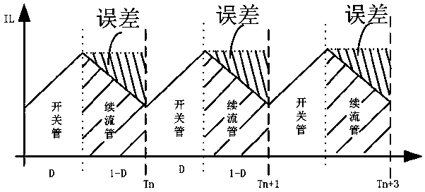
[0038] The basic principle of inductive switching power converters is to use the energy storage characteristics of the inductor to achieve voltage changes. The rate of change of the inductor current is equal to the voltage across the inductor divided by the inductor Henry value, which is expressed as ; The change of the inductor current is a linear process. The change speed of the inductor current is the slope of the linear change of the inductor current and the voltage across the inductor and the inductance value are related. When the applied voltage across the inductor is constant, the inductance value is also determined. The rising and falling slopes are also fixed.

[0039] In the existing boost type Boost type switching power supply converter circuit and the negative voltage Buck-Boost type switching power supply converter circuit, the two power tubes are...


PUM


Abstract

The invention discloses a load current detection circuit and method for a switching power supply converter. Only a switching tube peak current sampling circuit, a sampling hold circuit, an inductive current compensation circuit and a low-pass filter circuit need to be arranged; the method comprises the following steps: sampling to obtain a peak current of the Boost type or Buck-Boost type switching power supply converter in an inductive current rising period, namely a switching tube conduction period, in a current switching period; sampling and holding a peak current sampling value of an inductive current rising period, namely a switching tube conduction period, through a sampling and holding circuit; and in the conduction period of the follow current tube, compensating the peak current sampling value in the conduction period of the switching tube through the inductive current compensation circuit, outputting the compensated inductive current signal to the low-pass filter after being maintained by the sample hold circuit, and acquiring the load current signal of the switching power supply converter after being smoothed by the low-pass filter. The circuit is simplified, the detection accuracy and reliability are improved, and the cost and power consumption are reduced.

Description

Technical field [0001] The invention relates to the technical field of switching power supply converter circuits, in particular to a switching power supply converter load current detection method and circuit, which reduces the complexity of the load current detection circuit and improves the accuracy of load current detection. Background technique [0002] Switching power converter circuit is one of the most important types of power-to-voltage converters. It is mainly suitable for voltage conversion. The circuit form of DC / DC switching power converter includes a charge pump circuit realized by a capacitor and an inductor. Realized step-down Buck switch circuit, step-up Boost circuit and negative voltage circuit Buck-Boost circuit. In order to accurately control the current in the switching power converter circuit, it is necessary to accurately detect the load current. [0003] In the prior art, one of the commonly used load current detection methods is as attached figure 2 In the ...

Claims


Application Information

Patent Timeline
IPC IPC(8): H02M3/156H02M3/158
CPCH02M3/156H02M3/1582H02M1/0009H02M3/1566
Inventor 张海波李盛峰柏志彬黄令华
Owner 江苏华芯智造半导体有限公司
Why Eureka
Try Eureka