Double-drum settling denitration chamber jet lower gas inlet fuel gas and fuel oil corner tube boiler

A corner tube boiler and double drum technology, which is applied to water tube steam boilers, boiler water tubes, steam boilers, etc., can solve the problems of high concentration of nitrogen oxides, boilers that cannot meet the emission requirements, and pollute the environment, so as to reduce emissions, Simple structure and effect of improving thermal efficiency

Pending Publication Date: 2020-04-03
HARBIN SIFANG BOILER
View PDF0 Cites 0 Cited by
  • Summary
  • Abstract
  • Description
  • Claims
  • Application Information

AI Technical Summary

Problems solved by technology

With the increasingly stringent national environmental protection policies, the well-known structural boilers cannot meet the national emission requirements for boiler air pollution emission standards, and the concentration of nitrogen oxides is high, polluting the environment

Method used


Image

  • Double-drum settling denitration chamber jet lower gas inlet fuel gas and fuel oil corner tube boiler
  • Double-drum settling denitration chamber jet lower gas inlet fuel gas and fuel oil corner tube boiler

Examples


Embodiment 1

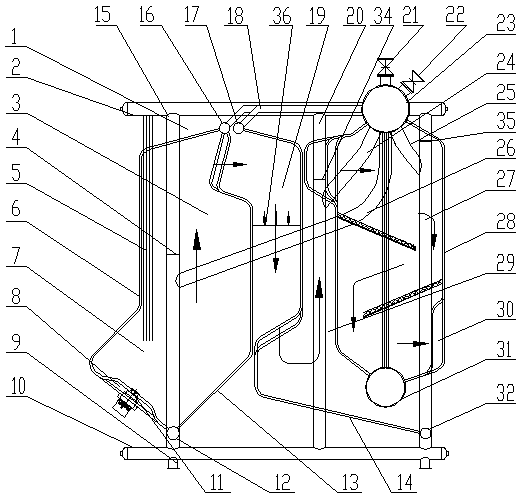
[0022] The invention provides a double-drum subsidence denitrification chamber injection gas-fired corner-tube boiler, such as figure 1 As shown, it includes the boiler body part and the combustion system part. The furnace body part of the boiler includes a boiler body 1, and six front side support downpipes 15, a first throttling ring 4, a middle support downpipe 20, a second throttling ring 34, The rear side supports the downcomer 27, the third throttle ring 35, the upper drum 23 and the lower drum 31 arranged on the upper right part of the boiler body 1, the convection tube bundle 28 between the upper drum and the lower drum, and the upper drum 23 Connected water inlet pipe 22 and outlet pipe 21, front downpipe 26, side downpipe 24, rear downpipe 25, upper return pipe 18, side water wall 5, side water wall lower header 10, side water wall upper header 2. The upper part of the furnace 3, the lower part of the oblique lower intake furnace 7, the front arch water wall 6, the ...

Embodiment 2

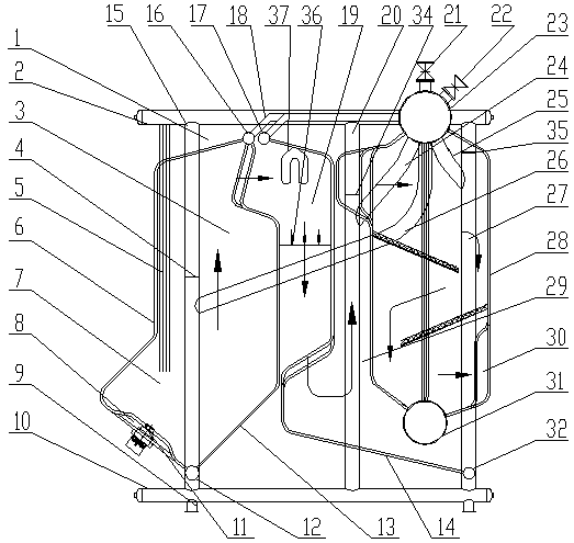
[0030] This embodiment is a further improvement made on the basis of Embodiment 1, including all the technical features of Embodiment 1, such as figure 2 As shown, a superheater is installed on the upper part of the upper sedimentation denitrification chamber.

[0031] The working process and principle of the present invention are as follows: firstly, fuel gas is injected into the furnace 7 and 3 through the gas (fuel) inlet 8 through the oblique burner 11 for combustion, and the heat generated is absorbed by the front arch water wall 6 of the furnace and the rear arch water wall 6. The arched water wall 13 is absorbed by the side water wall 5, and the cooled flue gas passes through the upper sedimentation denitrification chamber 19, descends, enters the lower sedimentation denitrification chamber 29, ascends, enters the convection tube bundle 28 for flushing and heat exchange, and completes the entire heat exchange process. The flue gas outlet 30 is discharged to complete th...


PUM


Abstract

The invention discloses a double-drum settling denitration chamber jet lower gas inlet fuel gas and fuel oil corner tube boiler. The corner tube boiler comprises a boiler body part and a combustion system part. A supporting structure is arranged in the boiler body and comprises a front side supporting downcomer, a middle supporting downcomer and a rear side supporting downcomer which are vertically arranged. A drum is arranged above one side of the boiler body; the drum is connected with a water inlet pipe; the bottom of the drum is connected with a downcomer communicated with the front side supporting downcomer, the middle supporting downcomer and the rear side supporting downcomer; the bottom of the front side supporting downcomer is connected with a front-back arch lower header; a front-back arch upper header communicated with the front-back arch lower header is arranged on the upper portion in the boiler body; and the front-back arch upper header is communicated with the drum through an upper water return pipe. Fuel stays for a long time, flames can freely extend, the fuel is fully combusted, the supporting structure and water circulation are safe, nitrogen oxide emission is reduced, boiler heat efficiency is improved, and the structure is simple.

Description

technical field [0001] The invention relates to the technical field of boilers, in particular, it can meet the emission requirements of the national boiler air pollutant emission standards, and solve the problems of insufficient fuel combustion, high nitrogen oxide emission concentration, and environmental pollution. Gas oil corner tube boiler. Background technique [0002] As we all know, the current gas-fired boilers generally have side air intake, the distance between the front and rear of the combustion chamber is short, the height of the combustion chamber is low, the volume of the combustion chamber is small, there is no settlement denitrification chamber, and the support structure and water circulation are not safe. This structure leads to short residence time of the flue gas and needs to turn to enter the upper part of the furnace, the flame cannot stretch freely, the gas combustion is uneven, the fuel combustion is insufficient, the flue gas filling degree of the co...

Claims


Application Information

Patent Timeline
Patent Type & Authority Applications(China)
IPC IPC(8): F22B21/04F22B31/00F22B37/10F24H1/44F24H9/18F24H9/00F23J15/00F23J15/02
CPCF22B21/04F22B31/00F22B37/10F23J15/003F23J15/02F23J2215/10F24H1/44F24H9/0005F24H9/1836
Inventor 杜晶房春雪孙伟东
Owner HARBIN SIFANG BOILER
Why Eureka
Try Eureka