
A manufacturing process of an annular heat accumulator and the annular heat accumulator

A production process and technology of heat accumulator, applied in heat storage equipment, heat exchanger types, indirect heat exchangers, etc., can solve the problems of different useless volumes, easy curling, uneven wire mesh, etc., and achieve the efficiency of heat accumulator. High, low heat flow loss, good reliability

Active Publication Date: 2020-12-08
CSIC SHANGHAI NEW ENERGY
View PDF10 Cites 0 Cited by
  • Summary
  • Abstract
  • Description
  • Claims
  • Application Information

AI Technical Summary

Problems solved by technology

[0005] The traditional wire mesh filling process is to fill the regenerator cavity with pieces of wire mesh. Due to the uneven and easy-to-curl characteristics of the wire mesh, the porosity of the regenerator cannot be precisely controlled during filling. Because there are gaps between the nets, the useless volume of the heat accumulator is different, so the consistency of the heat accumulator in the production process is difficult to control
[0006] The process of installing the traditional wire mesh on the regenerator cylinder after sintering also has the problem of different porosity of the wire mesh after sintering
At the same time, there is also sintering deformation. Different batches of regenerators have different sintering heights, and it is difficult to accurately control the height of the regenerator. As a result, the useless volume between the regenerator and the heater or cooler is different, which leads to inconsistent performance of each cylinder of the engine.

Method used


Image

  • A manufacturing process of an annular heat accumulator and the annular heat accumulator
  • A manufacturing process of an annular heat accumulator and the annular heat accumulator
  • A manufacturing process of an annular heat accumulator and the annular heat accumulator

Examples


Embodiment 2

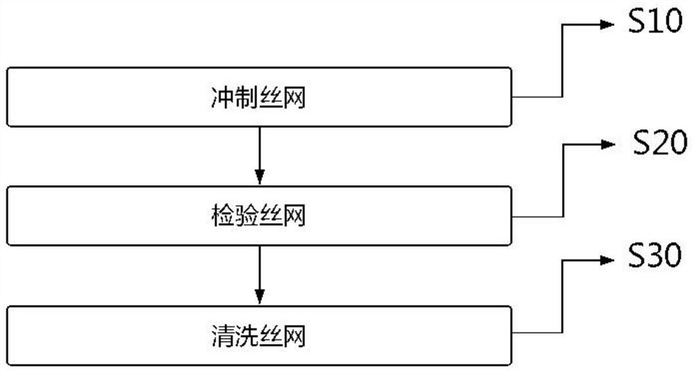
[0067] Embodiment two, on the basis of embodiment one, such as figure 2 As shown, the flow chart of making silk screen.

[0068] Concretely, before the silk screen weighing in step S100 includes making the silk screen, it specifically includes the following steps:

[0069] Step S10: punching the screen;

[0070] Step S20: inspecting the quality of the silk screen;

[0071] Step S30: cleaning the screen.

[0072] Fabricating the wire mesh through the above steps can meet the quality requirements of the annular heat accumulator 100 for the wire mesh.

Embodiment 3

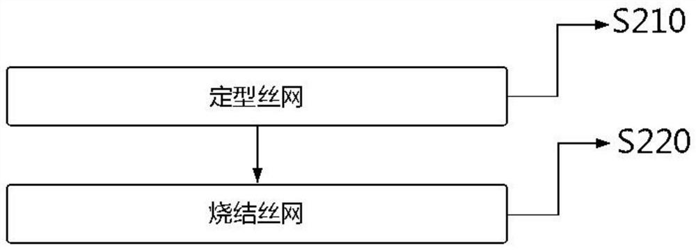
[0073] Embodiment three, on the basis of embodiment two, such as image 3 Shown, the flow chart of making screen sintered block 101.

[0074] Specifically, step S200 includes the following steps:

[0075] Such as Figure 4 As shown, step S210: shape the screen and apply pressure to obtain a shaped part of the screen;

[0076] Step S220: After unloading the sizing pressure, sintering the stenciled wire mesh part.

[0077] The above steps can solve the problem of unevenness and easy curling of the wire mesh, and further solve the gap between the wire mesh and the wire mesh, so that the porosity of the annular heat accumulator 100 can be precisely controlled, so the annular heat accumulator 100 The consistency can be precisely controlled.

Embodiment 4

[0078] Embodiment four, on the basis of embodiment three, such as Figure 5 As shown, the flow chart of the subsequent fabrication process.

[0079] Specifically, step S500 also includes the following steps:

[0080] Such as Figure 6 As shown, step S510: thermal sleeve of the outer sleeve, put the outer sleeve 103 of the heat accumulator into an oven for heating, and heat the outer sleeve 103 of the heat accumulator to the sintered block 101 after heating, so as to ensure the storage capacity during assembly. The bottom support of the heater outer sleeve 103 is attached to the screen sintered block 101 . A machining allowance of 0.2-0.4 mm should be left on the outer surface of the heat accumulator outer sleeve 103;

[0081] Such as Figure 7 As shown, step S520: component assembly, assemble the lower support ring 104 on the above-mentioned assembly, and add adhesive and nickel-based solder at the contact position between the lower support ring 104 and the assembly (the b...


PUM


Abstract

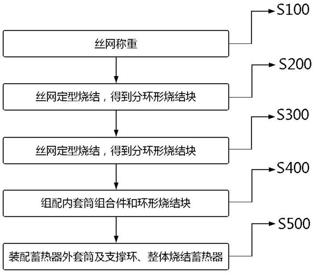
The invention provides a manufacturing process of an annular heat storer and the annular heat storer. The annular heat storer is provided with a silk screen sintering block, an inner sleeve combination piece, a heat storer outer sleeve and a support ring. The manufacturing process is characterized by comprising the steps of (S100) weighing a silk screen, (S200) shaping and sintering the silk screen to obtain separated annular sintered blocks, (S300) measuring the sizes of the separated annular sintered blocks, and selecting multiple separated annular sintered blocks for assembly, wherein the assembly height is a designed height of the silk screen sintered block, (S400) assembling the inner sleeve combination piece and the annular sintered blocks and (S500) assembling the heat storer outersleeve and the support ring for sintering to obtain a heat storer finished product. Through rolling of the silk screen sintering block, the outer side wall of the silk screen sintering block is smooth. Silk screens are divided into thin silk screens and thick silk screens; the thick silk screens are positioned at the two ends of the silk screen sintering block; and the thin silk screens are positioned in the silk screen sintering block.

Description

technical field [0001] The invention relates to the technical field of engines, in particular to a manufacturing process of an annular heat accumulator and the annular heat accumulator. Background technique [0002] The Stirling engine is a kind of special engine, and the Stirling engine can be used in underwater special environments or in the field of photothermal power generation. [0003] The heat accumulator is a key component of the Stirling engine, and its performance directly affects the performance of the engine. For the Stirling cycle, the gas flow path is usually composed of a heater, a heat accumulator, and a cooler. The heat accumulator is an intermediate link in the entire gas flow path. Under the high-speed oscillating reciprocating flow of working fluid, there is a temperature difference of about 700 degrees from the top to the bottom of the heat accumulator. [0004] The power loss of the Stirling engine mainly comes from the heat accumulator, and the power...

Claims


Application Information

Patent Timeline
IPC IPC(8): F28D20/00
CPCF28D20/00F28D2020/0004Y02E60/14
Inventor 梁鹏飞冯泳程张冲武超
Owner CSIC SHANGHAI NEW ENERGY
Learn More