
Treatment device and treatment method for CO2 flooding produced water

A technology of a treatment device and a treatment method, applied in the field of water treatment, can solve the problems of high cost of chemicals, poor flexibility, secondary pollution of the surrounding environment, etc., and achieve the effects of good treatment effect, high flexibility and small footprint

Active Publication Date: 2020-04-07
DAQING OILFIELD CO LTD +1
View PDF4 Cites 2 Cited by
  • Summary
  • Abstract
  • Description
  • Claims
  • Application Information

AI Technical Summary

Problems solved by technology

[0005] However, at present, there is no treatment system dedicated to the produced water of carbon dioxide flooding in oilfields. The produced water from carbon dioxide flooding is mixed with the produced water from water flooding and then treated by the water flooding produced water treatment system
For the water flooding produced water treatment system, this is equivalent to increasing the carbon dioxide content in the water flooding produced water, which will lead to frequent scaling and corrosion under the scale of the treatment equipment, which in turn will cause a large number of pipelines and water treatment equipment for produced water. Corrosion and perforation, can not be used normally
It can be seen that the original water flooding equipment can no longer adapt to the carbon dioxide flooding produced water in terms of scaling and corrosion.
In addition, the treatment system of conventional water flooding produced water occupies a large area, and the treatment process (natural settlement + coagulation settlement + quartz sand filtration and other physical methods and / or chemical methods such as scale inhibitors and corrosion inhibitors) has poor flexibility , Corrosion control and descaling effects are poor, and the cost of chemicals is high. After use, it may cause secondary pollution to the surrounding environment. It is difficult to meet normal production and environmental protection requirements such as oilfield anti-scaling, corrosion control, and reducing the frequency of equipment and pipeline replacement.

Method used


Image

  • Treatment device and treatment method for CO2 flooding produced water
  • Treatment device and treatment method for CO2 flooding produced water
  • Treatment device and treatment method for CO2 flooding produced water

Examples


Embodiment Construction

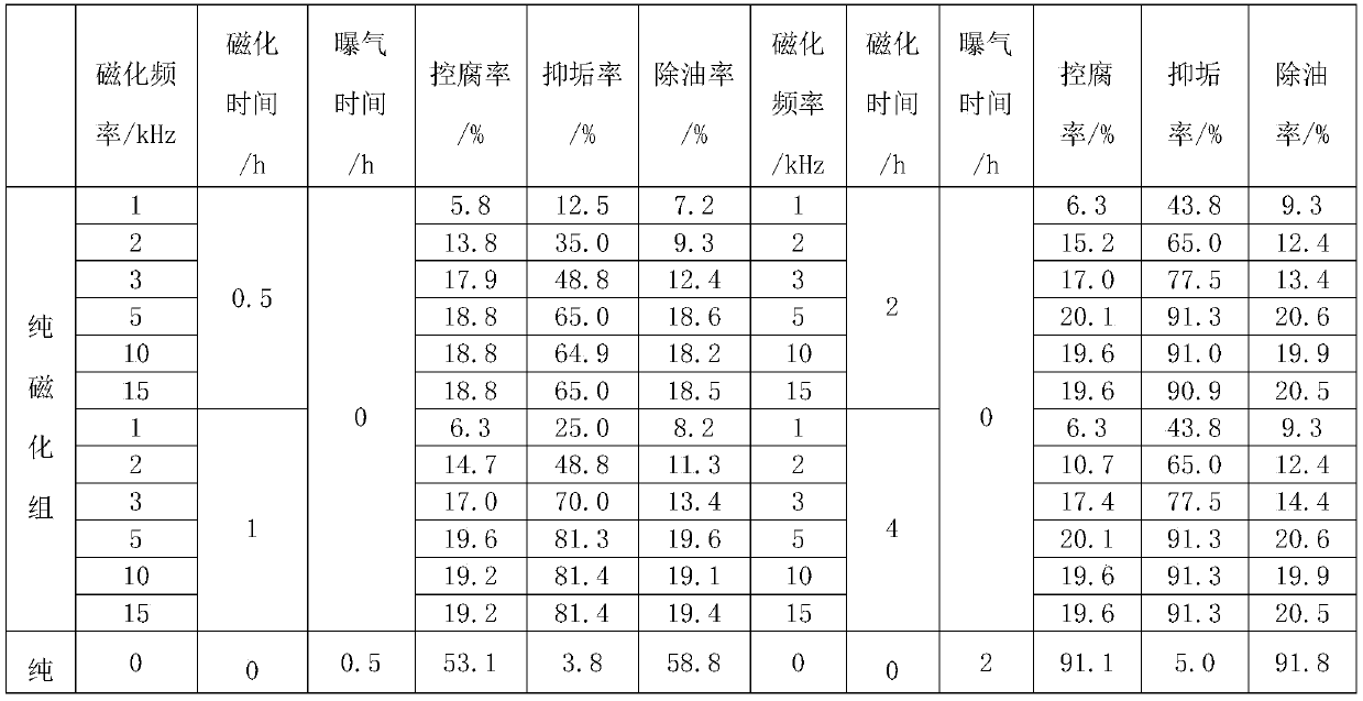
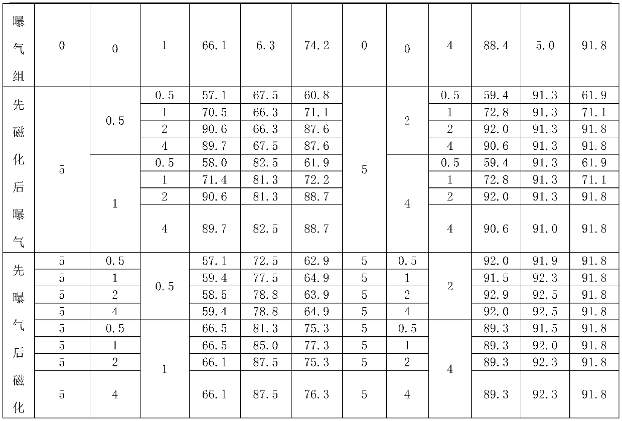
[0021] CO of the present invention 2 The frequency conversion electromagnetic aeration method is used to treat CO in the treatment device of flooding produced water 2 According to different water samples, four treatment methods can be used to treat the produced water: pure aeration, pure magnetization, first magnetization and then aeration, and first aeration and then magnetization. In addition, treatment effects can be evaluated to determine CO 2 Treatment methods of produced water.

[0022] In order to solve CO 2 The problem that the treatment system of the produced water is easy to scale, the treatment device of the present invention adopts the frequency conversion electromagnetic method to treat CO 2 Drive produced water. At present, the frequency conversion electromagnetic method is mainly used for the treatment of circulating water in thermal power plants, etc. The characteristics and composition of the treated water are relatively simple, which is different from tha...


PUM


Abstract

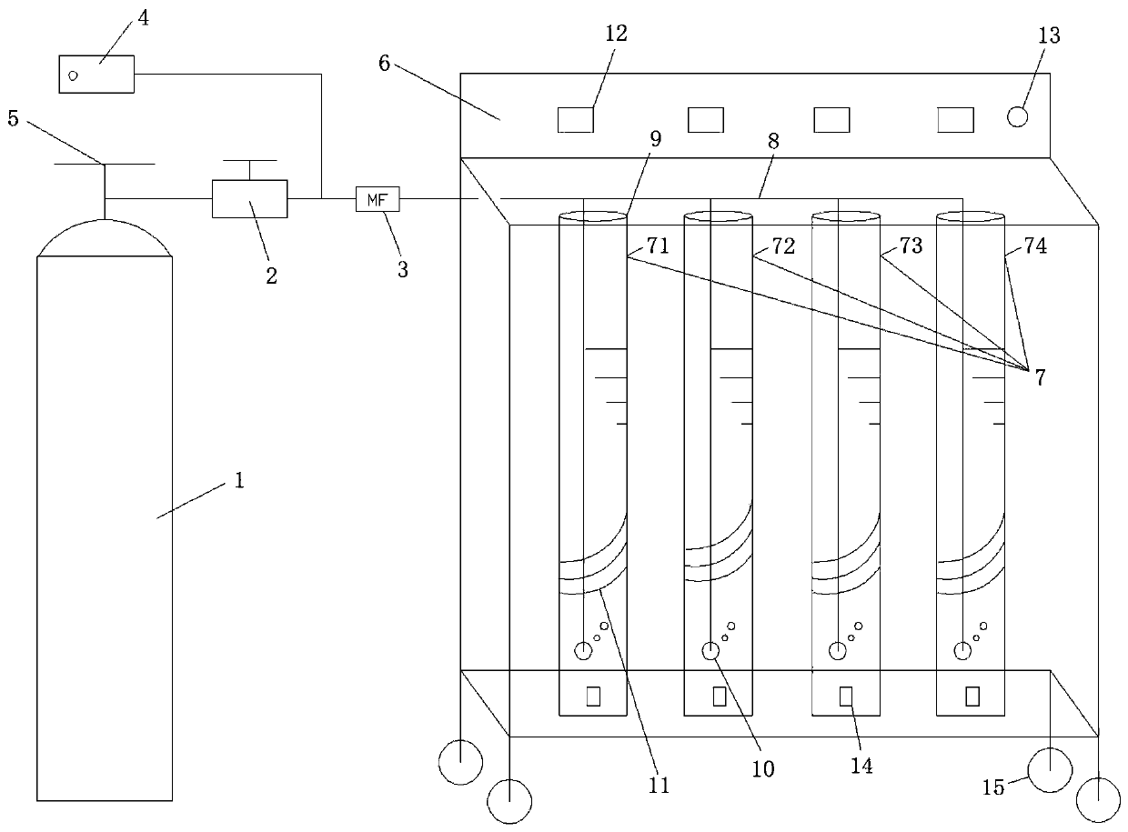
The invention discloses a treatment device and a treatment method for CO2 flooding produced water. The device comprises a test device main box body, a plurality of hollow ventilation test columns arearranged in the test device main box body, a water inlet is arranged at the top of each ventilation test column, a sewage sampling port is arranged at the bottom of each ventilation test column, an electromagnetic coil is wound on the surface of the outer wall of each ventilation test column, and an aeration head is arranged below the internal of each ventilation test column. The treatment devicehas the characteristics of high flexibility, small occupied area and good scale prevention and corrosion control treatment effects, and can be used for effectively carrying out oil removal, scale removal and corrosion control treatment on CO2 flooding produced water.

Description

technical field [0001] The invention relates to the technical field of water treatment, in particular to a method of using frequency conversion electromagnetic magnetization and aeration as CO 2 The treatment device of the flooding water treatment method, and the treatment of CO by this device 2 A method of flooding produced water for treatment. Background technique [0002] During oil field development, different oil displacement methods such as water flooding, polymer flooding, and ASP flooding are used for oil displacement. Specifically, oil displacement is: injecting water and oil displacement agent into the ground through the injection well. Since the oil displacement agent can improve the thickening ability of crude oil and reduce the interfacial tension of crude oil, it has the ability to wash oil, thereby dissolving the crude oil in the formation. ,carry. In this process, the oil-displacing agent and crude oil form an oil-water-gas mixture (ie, production fluid), ...

Claims


Application Information

Patent Timeline
IPC IPC(8): C02F9/12C02F103/10
CPCC02F1/48C02F7/00C02F2103/10C02F2201/483C02F2303/22Y02W10/10
Inventor 刘国宇冯涛陈忠喜曹振锟王可达夏福军孟岚
Owner DAQING OILFIELD CO LTD
Learn More