Lamb wave tomography method for defects of large storage tank bottom plate

A technology of tomography and large storage tanks, which is applied in the analysis of solids using sound waves/ultrasonic waves/infrasonic waves, material analysis and material analysis using sound waves/ultrasonic waves/infrasonic waves, and can solve problems such as difficult detection methods and susceptibility to corrosion , to achieve the effect of fast reconstruction, convenient use, and accurate defect location

Inactive Publication Date: 2020-04-07
UNIV OF ELECTRONICS SCI & TECH OF CHINA
View PDF7 Cites 0 Cited by
  • Summary
  • Abstract
  • Description
  • Claims
  • Application Information

AI Technical Summary

Problems solved by technology

The invention patent application with the application number 201410648212.0 discloses a non-contact ultrasonic detection method for storage tank floor corrosion based on dynamic wavelet fingerprint technology. Although this method does not directly contact the steel plate, the coupling method is actually a water immersion method. The steel plate to be tested must be immersed in water and is susceptible to corrosion. For large storage tanks, it is difficult to adopt a detection method in practical applications

Method used


Image

  • Lamb wave tomography method for defects of large storage tank bottom plate
  • Lamb wave tomography method for defects of large storage tank bottom plate
  • Lamb wave tomography method for defects of large storage tank bottom plate

Examples


Embodiment Construction

[0026] The present invention is specifically described below through the examples, it is necessary to point out that the present examples are only used to further illustrate the present invention, and can not be interpreted as limiting the protection scope of the invention, those skilled in the art can according to the above-mentioned present invention Some non-essential improvements and adjustments made in the content of the invention.

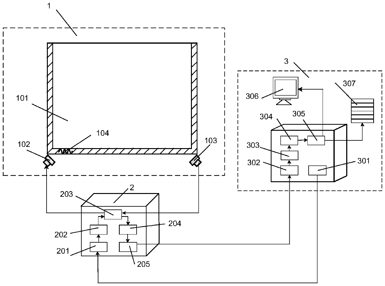
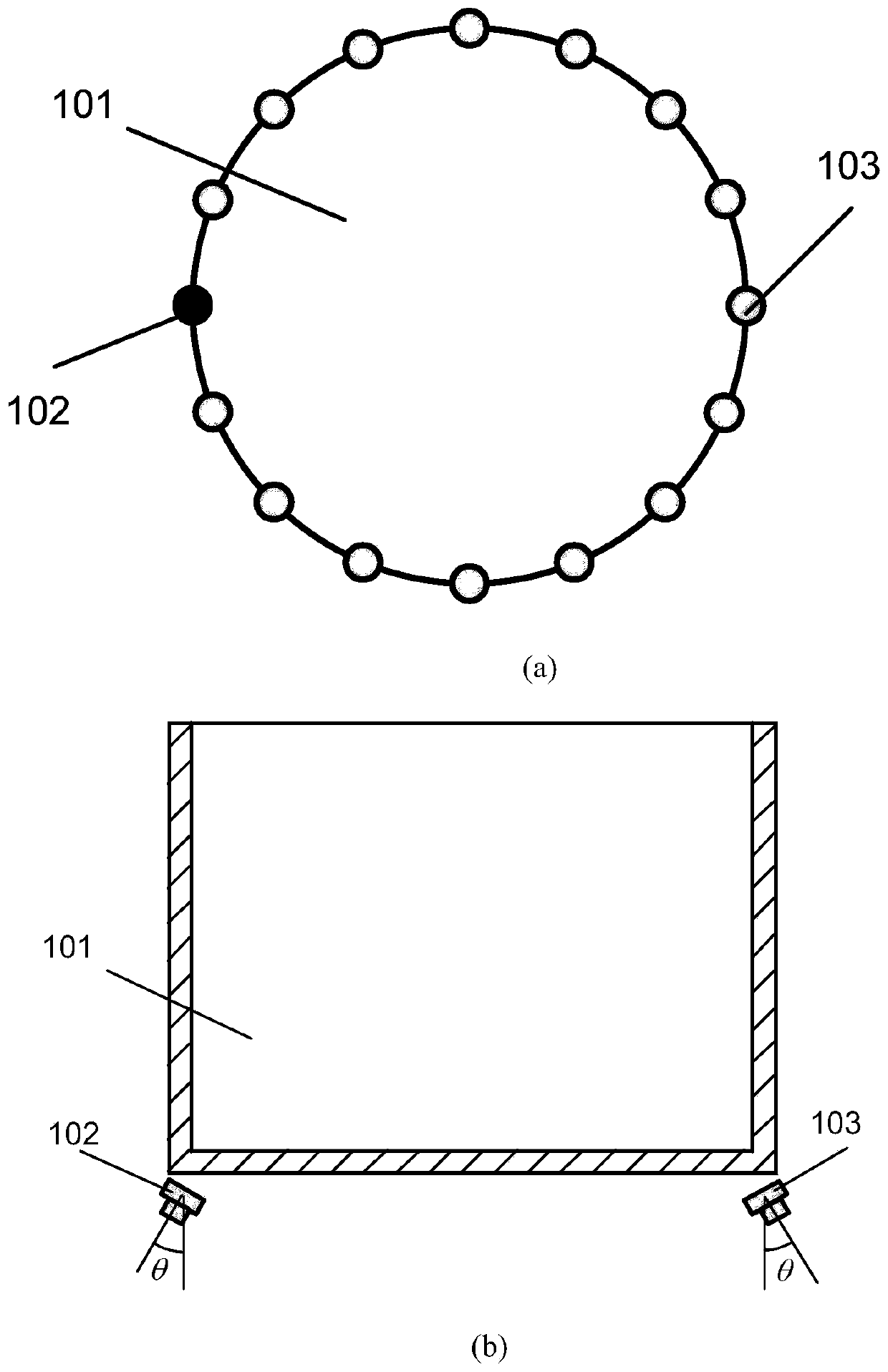
[0027] Such as figure 1 As shown, the system device of this embodiment mainly includes three parts: a detection unit 1 , a signal excitation receiving unit 2 and a computer unit 3 . The workpiece 101 to be detected in the detection module 1 is the bottom plate of the storage tank. The shape of the bottom plate is circular, and several air-coupled transducers are arranged equiangularly along its circumferential boundary, one of which is used as the excitation end 102 of the air-coupled transducer, and the rest are used as The receiving end 10...


PUM


Abstract

The invention discloses a tomography method for a circular bottom plate structure of a large storage tank, which is characterized in that air coupling transducers which are arranged along the circumference of a bottom plate of a storage tank at equal angular distances are used for collecting lamb wave signals, so that the defects of corrosion, rusting, pressure sensitivity and the like possibly existing in a contact type transducer due to the use of a coupling agent are avoided; by setting the included angle between the surface of the air coupling transducer and the surface of a detection workpiece, travel time information of a lamb wave single mode is obtained, and the difficulty of single mode signal extraction caused by frequency dispersion characteristics of the lamb wave is avoided; and an equal-angular-distance differential filtering back projection algorithm suitable for the circular bottom plate is derived, and the Lamb wave travel time information is subjected to differential,filtering and back projection operations in sequence to obtain the tomographic image of the circular storage tank bottom plate structure. The method has the advantages of the wide detection object range, the high reconstruction speed, convenience in use, the accurate defect positioning and the like, and a method support is provided for detecting defects, particularly corrosion defects, of the circular storage tank bottom plate structure.

Description

technical field [0001] The invention belongs to the field of ultrasonic non-destructive testing, in particular to a Lamb wave tomographic imaging method suitable for non-contact air coupling transducers arranged according to the pitch of circular holes. Background technique [0002] Large storage tanks used to store crude oil and gas are widely used in the energy industry. Domestic petroleum, chemical, port and other enterprises have tens of thousands of large storage tanks. During the long-term production and use of storage tanks, affected by factors such as medium, pressure and temperature, there will be defects such as corrosion, erosion, fatigue cracking and even perforation in varying degrees, resulting in structural failure and even leakage. Most of the materials stored in the storage tank are flammable, explosive, toxic and other substances. Once leaked, it will cause low temperature, combustion explosion, suffocation and rapid phase change hazards, resulting in fire,...

Claims


Application Information

Patent Timeline
Patent Type & Authority Applications(China)
IPC IPC(8): G01N29/04G01N29/06G01N29/36
CPCG01N29/041G01N29/0672G01N29/36G01N2291/0427G01N2291/2695
Inventor 王瑜李迅波曾毅星王洪艳董一凡
Owner UNIV OF ELECTRONICS SCI & TECH OF CHINA
Why Eureka
Try Eureka