
Microfluidic alveolar chip and alveolar breathing simulator

A microfluidic, alveolar technology, applied in teaching models, chemical instruments and methods, containers for laboratory use, etc., can solve the problems of complex structure, inaccurate overall research, and complicated control of breathing process, and achieve simple structure, Improve the accuracy of research and eliminate the effects of mutual interference and mutual restriction

Active Publication Date: 2022-01-21
HARBIN INST OF TECH SHENZHEN GRADUATE SCHOOL
View PDF8 Cites 0 Cited by
  • Summary
  • Abstract
  • Description
  • Claims
  • Application Information

AI Technical Summary

Problems solved by technology

However, the structure of the above five levels of alveolar tree structure is relatively complex, and the size of alveolar ducts and alveoli at each level is the same, while the real alveolar tree structure decreases with the increase of alveolar levels, the diameter of alveolar ducts decreases, and the diameter of alveoli increases. Therefore, the existing The five-level alveolar tree structure does not conform to the real situation of the human alveolar tree structure, and the overall research is inaccurate; in addition, because the alveolar ducts at all levels are connected, the flows of each level interfere and restrict each other, the existing five-level alveolar tree structure and the real structure Inconsistency will cause the flow in the alveolar ducts at all levels to not be precisely controlled to match the actual situation, and some important phenomena, such as chaotic flow, will be ignored; and the breathing process control of the existing five-level alveolar tree branch structure is relatively complicated

Method used


Image

  • Microfluidic alveolar chip and alveolar breathing simulator
  • Microfluidic alveolar chip and alveolar breathing simulator
  • Microfluidic alveolar chip and alveolar breathing simulator

Examples


Embodiment Construction

[0025] The conception and technical effects of the present invention will be clearly and completely described below in conjunction with the embodiments, so as to fully understand the purpose, features and effects of the present invention. Apparently, the described embodiments are only some of the embodiments of the present invention, rather than all of them. Based on the embodiments of the present invention, other embodiments obtained by those skilled in the art without creative efforts belong to The protection scope of the present invention.

[0026] In the description of the embodiments of the present invention, if it involves orientation description, for example, the orientation or positional relationship indicated by "upper", "lower", "front", "back", "left", "right" etc. is based on the drawings The orientations or positional relationships shown are only for the convenience of describing the present invention and simplifying the description, and do not indicate or imply t...


PUM


Abstract

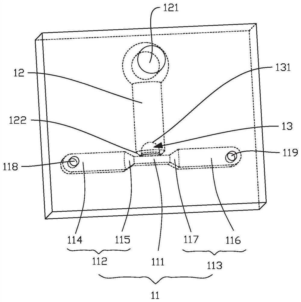
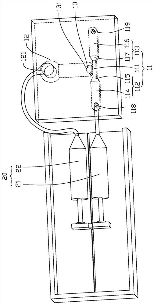
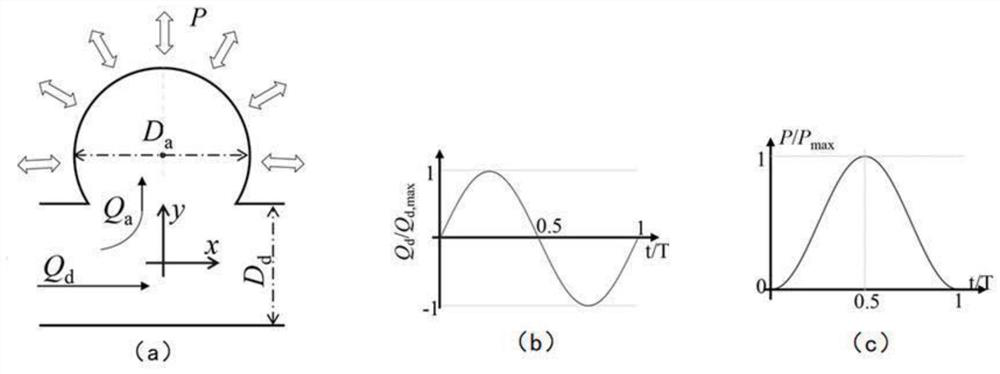
The invention discloses a microfluidic alveolar chip and an alveolar breathing simulation device. The microfluidic alveolar chip includes a microfluidic channel, a gas cavity and simulated alveoli; wherein the microfluidic channel includes a simulated alveolar channel, an auxiliary liquid inlet channel and Auxiliary liquid storage channel; both ends of the simulated alveolar duct have a fluid inlet and a fluid outlet, the fluid inlet is connected to the auxiliary liquid inlet channel, and the fluid outlet is connected to the auxiliary liquid storage channel; the auxiliary liquid inlet channel is provided with a liquid inlet; the gas cavity has The gas entrance and exit; the simulated alveoli include an inner cavity and an elastic side wall, and the inner cavity communicates with the simulated alveolar pipeline; the simulated alveoli are arranged in the gas cavity. The structure of the microfluidic alveolar chip of the present invention is simple, and the single alveolar structure microfluidic chip can be used to control the parameters separately, so as to study the complex flow field in the alveoli of each level separately, avoid mutual interference and mutual restriction between the flows of each level, and improve the accuracy of the research. sex.

Description

technical field [0001] The invention relates to the technical field of biomedical equipment, in particular to a microfluidic alveolar chip and an alveolar respiration simulation device. Background technique [0002] The main function of human respiration is to provide oxygen to various tissues of the body and remove carbon dioxide waste gas. The respiration process of the human body can be divided into two stages: the gas is delivered from the external environment to the blood; the gas enters various tissues through the blood. With the continuous progress of society and economy, human beings have continuously improved the quality requirements of the living environment, and their awareness of the protection of the living environment has gradually increased. Particulate pollution caused by industrial production and environmental degradation has become one of the important indicators for evaluating the quality of life and air quality. In atmospheric aerosol particle pollution,...

Claims


Application Information

Patent Timeline
Patent Type & Authority Patents(China)
IPC IPC(8): B01L3/00G09B23/28
CPCB01L3/502707B01L3/50273G09B23/28
Inventor 朱永刚吕慧敏裘岩董军杨月邓园博
Owner HARBIN INST OF TECH SHENZHEN GRADUATE SCHOOL
Learn More