High-voltage pulse track circuit receiver

A track circuit, high-voltage pulse technology, applied in railway signals, railway car body components, railway signals and safety, etc., can solve the problem of insufficient processing speed and accuracy of the receiver CPU, low return coefficient of binary poor relays, and anti-interference at the receiving end. Weak capabilities, etc., to achieve the effect of improving real-time and reliability, improving reliability and security, and high degree of automation

Inactive Publication Date: 2020-04-10
HUNAN VOCATIONAL COLLEGE OF RAILWAY TECH
View PDF0 Cites 1 Cited by
  • Summary
  • Abstract
  • Description
  • Claims
  • Application Information

AI Technical Summary

Problems solved by technology

In actual operation, the main problems exposed by the high-voltage pulse track circuit are the weak anti-interference ability of the receiving end, the low return coefficient of the binary poor relay, prone to malfunction, and the high voltage formed when the code sending end is no-load will cause the device to withstand voltage, Insufficient heat resistance and damage
Secondly, there is the problem that the processing speed and precision of the receiver CPU are not enough

Method used


Image

  • High-voltage pulse track circuit receiver
  • High-voltage pulse track circuit receiver
  • High-voltage pulse track circuit receiver

Examples


Embodiment 1

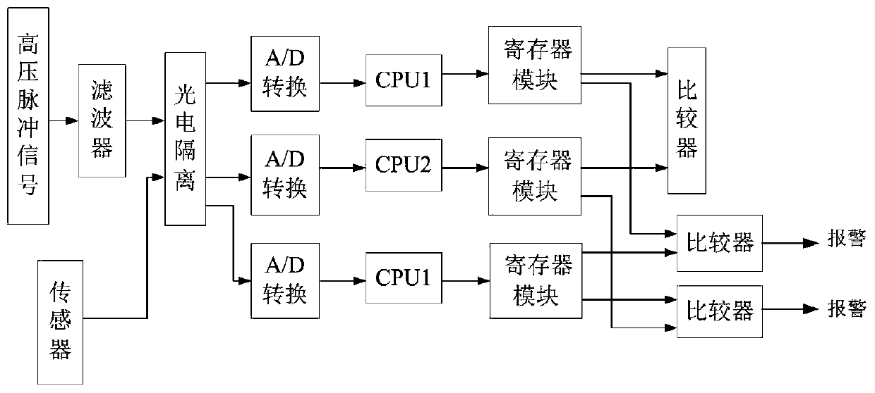
[0022] Such as figure 1 As shown, the high-voltage pulse track circuit receiver includes three acquisition channels, two signal processing units (central processing unit CPU) and three storage units (registers), acquisition channel one and acquisition channel three share signal processing units one and two Two output signals are respectively stored in two storage units, the acquisition channel two is connected to the signal processing unit two, and its output signal is stored in another storage unit, and the three storage units form a two-out-of-three structure and are respectively connected to the corresponding comparator (a total of three indivual).

[0023] The three acquisition channels include filters (Butterworth band-stop filter, which has a better filtering effect than band-pass filters), voltage sensors, photoelectric isolators and three A / D converters; acquisition channel 1 and acquisition channel 2 receive signals from The high-voltage pulse signal on the track cir...

Embodiment 2

[0029] Central processing unit CPU one among the present embodiment adopts base 2FFT fast processing method, suppose input sequence length is N=2M (M is a positive integer), decomposes the parity of this sequence into shorter and shorter subsequences by chronological order, The FFT method called radix-2 decimation in time. The calculation formula of FFT is as follows:

[0030]

[0031]

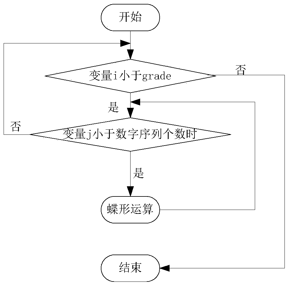
[0032] Among them, X(k) represents the first half of the sequence, and X(N / 2+k) represents the second half of the sequence. Similarly, the above two calculation formulas can be expressed by the butterfly algorithm, such as Figure 4 As shown, in the formula: (1) the two channels on the left are inputs; (2) the two channels on the right are outputs; (3) a small circle in the middle represents addition and subtraction operations (the upper right channel is the addition output, and the lower right channel is the phase minus output).

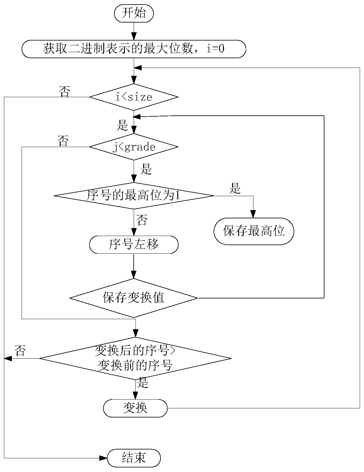
[0033] In the radix 2FFT butterfly operation extracted...


PUM


Abstract

A high-voltage pulse track circuit receiver belongs to the technical field of track circuits. The high-voltage pulse track circuit receiver comprises three acquisition channels, two signal processingunits and three storage units, the acquisition channel I and the acquisition channel III share the signal processing unit I, two output signals are respectively stored in two of the three storage units, the acquisition channel II is connected with the signal processing unit II, the output signal of the acquisition channel II is stored in another storage unit, and the three storage units form a two-out-of-three structure and are respectively connected to corresponding comparators. According to the high-voltage pulse track circuit receiver, two CPUs are mainly used for effectively acquiring andidentifying high-voltage pulse signals, the two CPUs respectively adopt different processing identification methods, the pulse signals are processed by the CPUs, and the operation results are comparedto be consistent by the comparators, so that whether a vehicle is occupied in an interval or not can be judged, and the reliability and the safety of the equipment are improved.

Description

technical field [0001] The invention belongs to the technical field of track circuits, and more specifically relates to a high-voltage pulse track circuit receiver. Background technique [0002] Track circuit is one of the important equipment to realize railway modernization and ensure the safe running of trains, and plays an important role in railway signaling system. The high-voltage pulse track circuit is the basic device used to detect whether the track is free or not. The high-voltage pulse generated by the high-voltage pulse track circuit has the characteristics of large instantaneous voltage and low current, and can break down impurities such as rust and oxide film on the surface of the rail. In actual operation, the main problems exposed by the high-voltage pulse track circuit are the weak anti-interference ability of the receiving end, the low return coefficient of the binary poor relay, prone to malfunction, and the high voltage formed when the code sending end is...

Claims


Application Information

Patent Timeline
Patent Type & Authority Applications(China)
IPC IPC(8): B61L1/18
CPCB61L1/18B61L1/181
Inventor 任建新王懿于训全周庞荣龙伟民辛芮霞郭立欣
Owner HUNAN VOCATIONAL COLLEGE OF RAILWAY TECH
Why Eureka
Try Eureka