
Chlor-alkali membrane electrolyzer with porous conductive plate

A conductive plate and membrane electrolysis technology, applied in the direction of electrolysis process, electrolysis components, electrodes, etc., can solve the problems such as the inability to achieve the increase of cell voltage, achieve the effect of reducing the mechanical performance requirements, eliminating the increase of cell voltage, and high electrolysis efficiency

Active Publication Date: 2021-05-28
SHANDONG DONGYUE POLYMER MATERIAL
View PDF8 Cites 0 Cited by
  • Summary
  • Abstract
  • Description
  • Claims
  • Application Information

AI Technical Summary

Problems solved by technology

However, in the cell body of this device, the function of completely eliminating the cell voltage increase caused by the cathode / anode electrolyte layer cannot be achieved, so that the development of ordinary chlor-alkali electrolyzers has not made breakthrough progress. The electrolysis process is due to electrolysis equipment. The reason why the real "zero pole distance" cannot be realized, this technical problem needs to be solved urgently

Method used


Image

  • Chlor-alkali membrane electrolyzer with porous conductive plate
  • Chlor-alkali membrane electrolyzer with porous conductive plate
  • Chlor-alkali membrane electrolyzer with porous conductive plate

Examples


Embodiment 1

[0027] Table 1 Summary table of electrolysis experiment results of different materials

[0028]

[0029] Here, the energy consumption is represented by the cell voltage, and the current density of each batch of experiments is 6kA / m 2 , as can be seen from Table 1, the energy consumption of carbon felt, sintered copper plate and nickel foam is higher than that of ordinary experimental tank. High, so continuous optimization is required.

Embodiment 2

[0031] The device of this embodiment is the same as that of Example 1. The experimental process is based on Example 1, and the optimization experiment is carried out on nickel foams of different thicknesses. The operating current density of each batch of experiments is 6kA / m 2 , other operating conditions and process are all the same as in Example 1, and the experimental results are shown in Table 2.

[0032] Table 2 Summary of electrolytic experiment results with different thicknesses of nickel foam

[0033]

[0034] Here, the energy consumption is also characterized by cell voltage. As can be seen from Table 3, the experimental effect of the nickel foam with a thickness of 0.2mm is better than that of nickel foam with 0.5mm and 1.0mm. From the data of this embodiment, it can be determined that the smaller the nickel foam with thickness The better the effect, but still need to continue to optimize.

Embodiment 3

[0036] The device of this embodiment is the same as that of Example 2. This experimental process is based on Example 2, and whether there is an active coating on the cathode filling material is tested, and the current density of each batch of experiments is 6kA / m 2 , other operating conditions and process are all the same as in Example 2, and the experimental results are shown in Table 3.

[0037] Table 3 Summary table of electrolytic experiment results with or without active coating

[0038]

[0039] Here, the cell voltage is also used to represent energy consumption. As can be seen from Table 2, the experimental effect of nickel foam with active coating is better than that of nickel foam without active coating, but the energy consumption of nickel foam with active coating is comparable to that of ordinary experimental tanks. The ratio is still slightly higher and needs to be continuously optimized.

[0040] The above results prove the novel chlor-alkali membrane electrol...


PUM

PropertyMeasurementUnit
thicknessaaaaaaaaaa
depthaaaaaaaaaa

Abstract

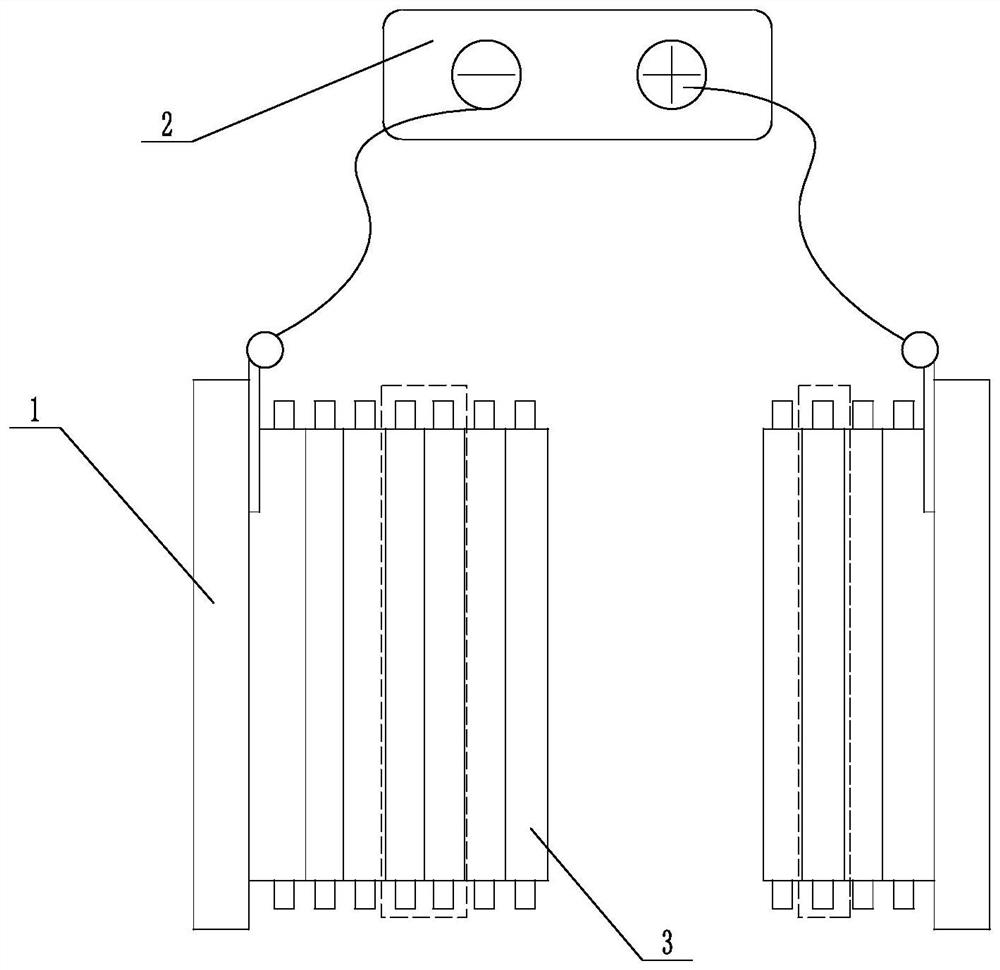
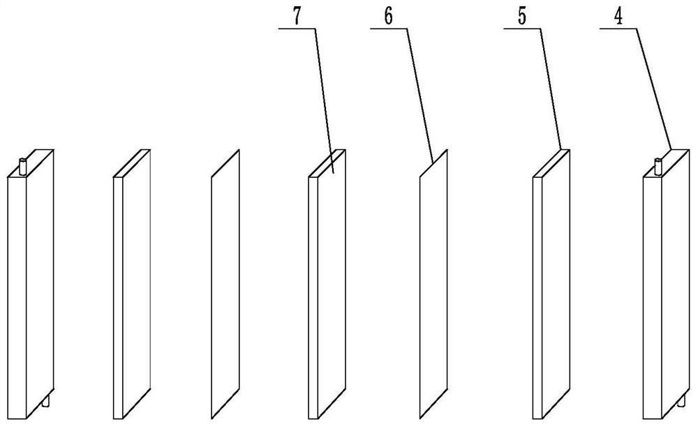
The invention relates to a chlor-alkali membrane electrolysis device, in particular to a chlor-alkali membrane electrolysis cell containing a porous conductive plate. An anode porous conductive material is filled between the anode of the electrolytic cell and the chlor-alkali membrane, and a cathode porous conductive material is filled between the cathode of the electrolytic cell and the chlor-alkali membrane. In the present invention, porous conductive materials are introduced into the cathode and the anode. On the one hand, the porous conductive materials can support the fluorine-containing ion exchange membrane, and can reduce the mechanical performance requirements of the fluorine-containing ion exchange membrane; on the other hand, the porous The type conductive material is not only an electron transport channel, but also a carrier for electrolytic catalysis, and the electrolytic efficiency is higher. The new structure makes full use of the advantages of the ordinary chlor-alkali electrolytic cell structure to improve it. In the structure, the porous conductive material and the membrane material are in zero-distance contact, so that the electrolysis process can truly achieve "zero pole distance" to eliminate the cathode / anode electrolyte layer. Slot voltage increment.

Description

technical field [0001] The invention relates to a chlor-alkali membrane electrolysis device, in particular to a chlor-alkali membrane electrolysis cell containing a porous conductive plate. Background technique [0002] Since the birth of the ion-exchange membrane electrolyzer in the 1970s, it has brought subversive development to the chlor-alkali industry. The energy consumption has been greatly reduced and the product quality has been significantly improved. However, in the face of the increasing shortage of energy, and the continuous strengthening of environmental protection management and energy-saving requirements by relevant national functional departments, the chlor-alkali industry has put forward higher goals and requirements for the energy-saving performance of electrolytic cells; and with the development of electrolysis technology, high current density And electrolyzers with low energy consumption have become the development trend of today's industry. Under high c...

Claims


Application Information

Patent Timeline
Patent Type & Authority Patents(China)
IPC IPC(8): C25B1/46C25B9/19C25B11/03
CPCC25B1/46C25B11/031C25B9/19
Inventor 张永明薛帅冯威张恒雷建龙
Owner SHANDONG DONGYUE POLYMER MATERIAL
Learn More