
Precise proppant placing method aiming at natural fracture development gas pool hydrofracture

A technology of natural fractures and hydraulic fracturing, which is applied in earth-moving drilling, production of fluids, wellbore/well components, etc., can solve the problems of poor stimulation and reconstruction effect of oil and gas reservoirs, inability to transport proppant, and low communication efficiency of natural fractures. Achieve the effect of improving the effect of increasing production, improving the laying efficiency, and optimizing the thickness of the perforation

Active Publication Date: 2020-04-10
SOUTHWEST PETROLEUM UNIV
View PDF4 Cites 1 Cited by
  • Summary
  • Abstract
  • Description
  • Claims
  • Application Information

AI Technical Summary

Problems solved by technology

[0005] At present, there are many design methods for optimizing hydraulic fracturing construction parameters at home and abroad, but there are few theories to optimize the design of hydraulic pressure construction parameters from the perspective of proppant settlement characteristics for intervals where natural fractures develop and form complex fracture networks. It cannot meet the current site construction design requirements, and the proppant cannot be accurately delivered to the target fractures during the fracturing construction process. The communication efficiency of natural fractures is low, and the stimulation effect on oil and gas reservoirs is poor.

Method used


Image

  • Precise proppant placing method aiming at natural fracture development gas pool hydrofracture
  • Precise proppant placing method aiming at natural fracture development gas pool hydrofracture
  • Precise proppant placing method aiming at natural fracture development gas pool hydrofracture

Examples


Embodiment

[0037] Taking single well C in an oilfield as an example, the well has developed natural fractures, the designed hydraulic fracturing interval has a burial depth of 3608.0-3625.0 m, an average formation temperature of 120 °C, and a formation closure pressure of 43 MPa.

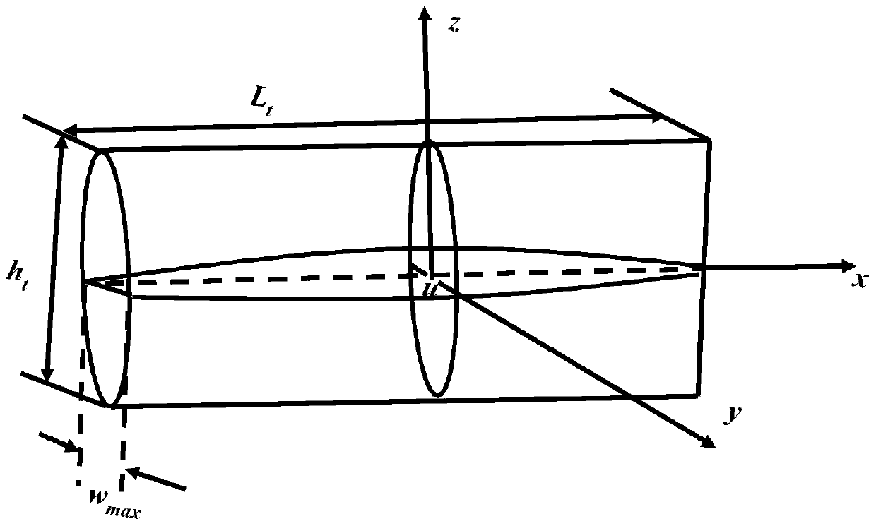
[0038] (1) According to the preliminary laboratory test results, the density of the fracturing fluid is 1250kg / m 3 , the fracturing fluid viscosity is 0.25Pa·s, the proppant particle diameter is 0.0006m, the sand ratio is 15% (that is, the volume fraction of liquid in the mixture of proppant and fracturing fluid is 89.7%), and the fracture closure time after stopping the pump 5000s, the vertical downward migration velocity of the sand-carrying fluid in the fracture is 0.002m / s, the casing fracturing wellbore radius is 39mm, the choke radius is 1.5mm, and the wellhead pressure during the flowback process is 2MPa;

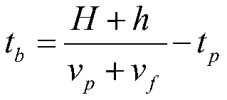
[0039] (2) Since the formation closure pressure P=43MPaz 1500kg / m 3 ; The liquid density ρ of th...


PUM


Abstract

The invention discloses a precise proppant placing method aiming at natural fracture development gas pool hydrofracture. Geological parameters and physical property parameters of a reservoir stratum are obtained according to certain single well logging interpretation, and the density of a proppant and the density of fracturing fluid are determined according to the stratum crack closure pressure ofthe reservoir stratum; the resistance to the proppant in the fluid migration process is determined according to the Reynolds number; the sedimentation height of the proppant in a crack is calculatedaccording to the crack closing time obtained after pumping is stopped and the migration speed of the proppant during flowing back; the weight of the crack formed by fracturing this time is calculatedaccording to the sedimentation height of the proppant in the crack; the sand-carrying fluid pumping time is calculated according to the target well perforation thickness and the sedimentation height of the proppant in the crack in combination with the crack closing time obtained after pumping is stopped; and finally, the proppant is laid according to the obtained fracturing construction parameters. According to the precise proppant placing method, the proppant is precisely conveyed to a fracturing transforming layer section developed by the natural fracture, the laying efficiency of the proppant is effectively improved, and the capacity increasing revamping effect is improved.

Description

technical field [0001] The invention relates to a method for accurately placing a proppant for hydraulic fracturing of gas reservoirs with natural fractures, and belongs to the technical field of petroleum engineering. Background technique [0002] Hydraulic fracturing technology is an important measure for oil and gas reservoir stimulation. Volume fracturing is a new fracturing technology for wells with natural fractures. The principle is to break and extend the formation with natural fractures to form three-dimensionally expanded complex fractures through hydraulic hydraulic action, and provide long-term fracture conductivity through the carrying and effective laying of proppant. At the same time, after fracturing flowback, The proppant left in the fracture prevents the fracture from completely closing, keeps the fracture open to a certain extent under the action of closure stress, forms a sand-filled fracture with a certain length and fluid flow in the formation, and fin...

Claims


Application Information

Patent Timeline
IPC IPC(8): E21B43/267
CPCE21B43/267
Inventor 卢聪李欣阳郭建春周丙部马莅罗扬吕传炳李彦国王朝辉黄枫岚
Owner SOUTHWEST PETROLEUM UNIV
Learn More