Low-energy-consumption long-service-life liquid nitrogen cooling machining device

A liquid nitrogen cooling and processing device technology, which is applied in the direction of metal processing equipment, metal processing machinery parts, manufacturing tools, etc., can solve the problems of brittle fracture of tools, large loss of nitrogen gas, high energy consumption of liquid nitrogen preparation, and prevent low temperature brittle fracture , Ease of replacement, and the effect of improving the convenience of replacement

Pending Publication Date: 2020-04-14
付炜亮
View PDF0 Cites 1 Cited by
  • Summary
  • Abstract
  • Description
  • Claims
  • Application Information

AI Technical Summary

Problems solved by technology

[0003] The purpose of the present invention is to provide a liquid nitrogen cooling processing device with low energy consumption and long service life to solve the problems of brittle fracture of cutting tools, large nitrogen loss and high energy consumption of liquid nitrogen preparation

Method used


Image

  • Low-energy-consumption long-service-life liquid nitrogen cooling machining device
  • Low-energy-consumption long-service-life liquid nitrogen cooling machining device
  • Low-energy-consumption long-service-life liquid nitrogen cooling machining device

Examples


Embodiment Construction

[0025] In order to make the purpose, technical solutions and advantages of the embodiments of the present invention clearer, the technical solutions in the embodiments of the present invention will be clearly and completely described below in conjunction with the accompanying drawings in the embodiments of the present invention. Obviously, the described embodiments It is some embodiments of the present invention, but not all of them. Based on the implementation manners in the present invention, all other implementation manners obtained by persons of ordinary skill in the art without creative efforts fall within the protection scope of the present invention.

[0026] Accordingly, the following detailed description of the embodiments of the invention provided in the accompanying drawings is not intended to limit the scope of the claimed invention, but merely represents selected embodiments of the invention. Based on the implementation manners in the present invention, all other ...


PUM


Abstract

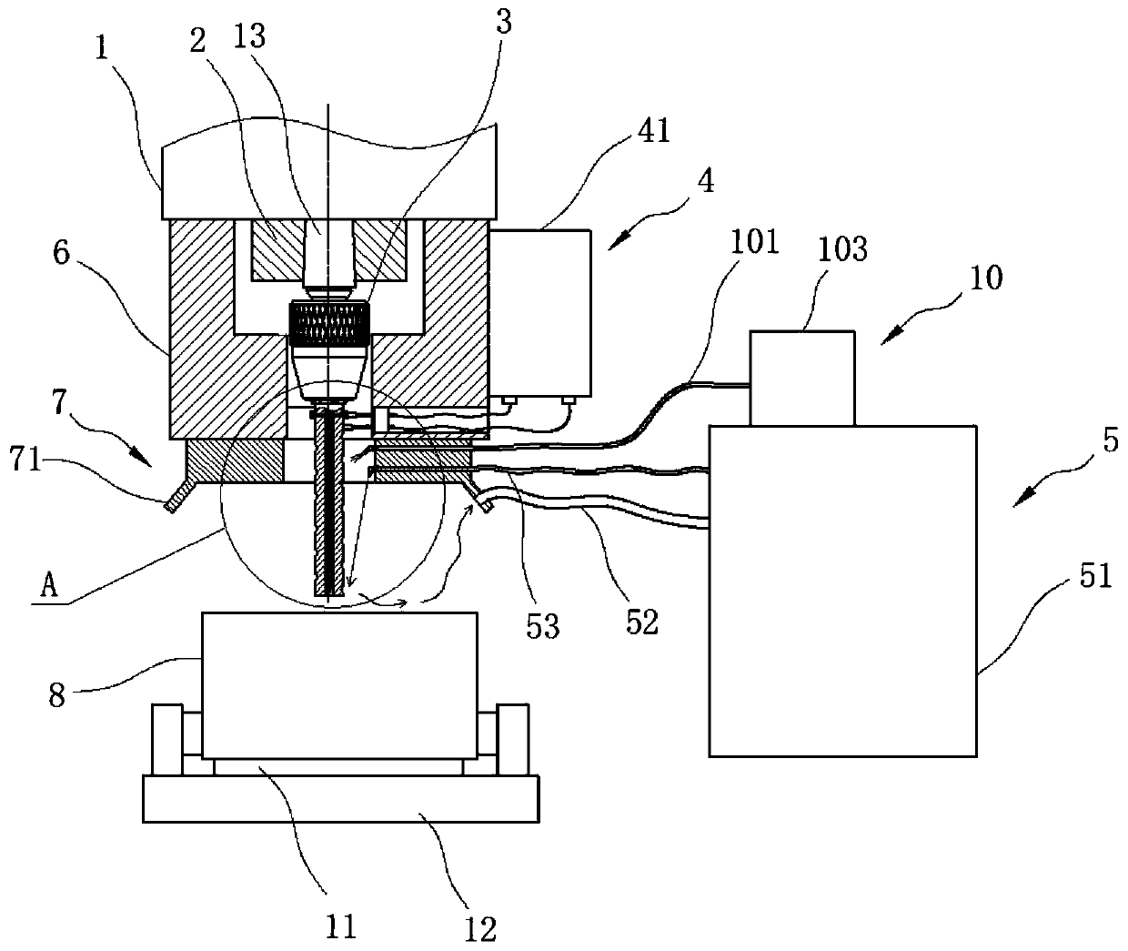
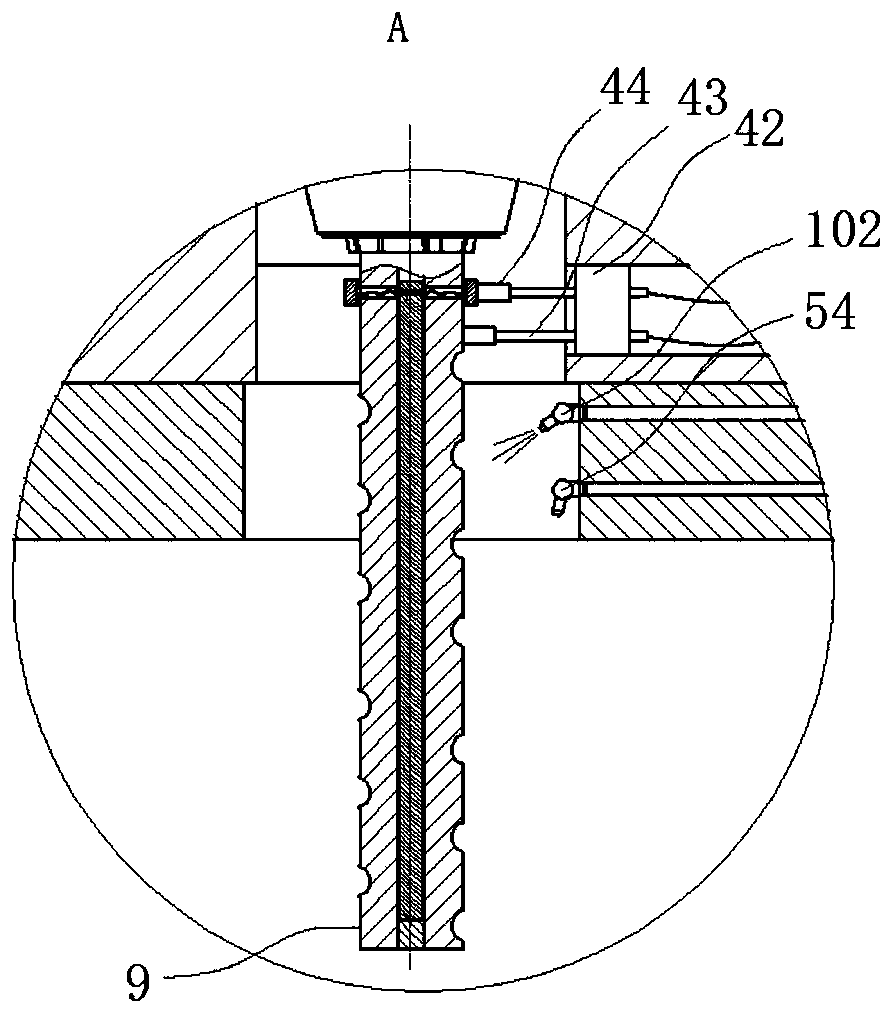
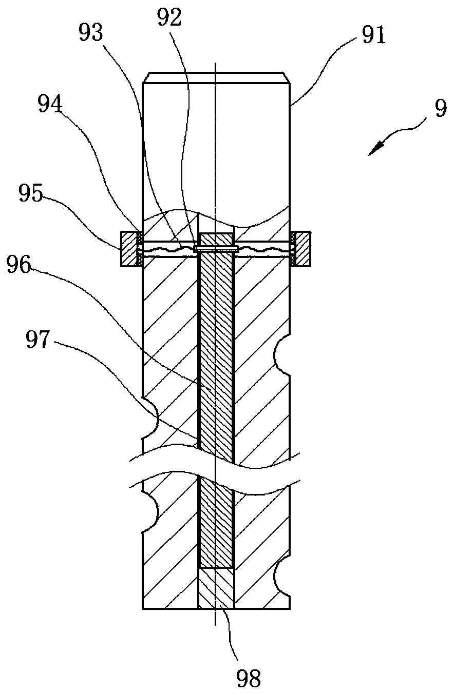
The invention relates to the technical field of metal cutting machining, in particular to a low-energy-consumption long-service-life liquid nitrogen cooling machining device. In the case of current liquid nitrogen cutting, local low temperature can be generated on a cutter, so that brittle fracture is caused, the service life of the cutter is relatively short, and the production cost is increased;and meanwhile, liquid nitrogen is rapidly vaporized after being sprayed, and then is dissipated into an external environment, so that the nitrogen loss is relatively large, and the energy consumptionof liquid nitrogen preparation is relatively high. According to the low-energy-consumption long-service-life liquid nitrogen cooling machining device, a liquid nitrogen spraying device is arranged onone side of a machine tool spindle seat and is connected with a collection disc to spray the liquid nitrogen to the lower end of a milling cutter assembly and recover nitrogen at the same time, a heating assembly is arranged in an inner hole of the milling cutter assembly, the heating assembly communicates with a power supply device for heating so that the nitrogen with the relatively low temperature can be recovered by the liquid nitrogen spraying device, the milling cutter assembly can be heated to prevent the brittle fracture, then the service life of the cutter is effectively prolonged, and the energy consumption of the liquid nitrogen preparation is reduced. The low-energy-consumption long-service-life liquid nitrogen cooling machining device is mainly used in the field of liquid nitrogen cooling machining devices.

Description

technical field [0001] The invention relates to the technical field of metal cutting, in particular to a liquid nitrogen cooling processing device with low energy consumption and long service life. Background technique [0002] Liquid nitrogen cooling cutting is a cutting method that uses a medium with a low boiling point of -196°C and uses the characteristics of liquid nitrogen to send the nitrogen generated by the nitrogen generator into the cutting point in the form of liquid nitrogen under pressure to replace a large amount of oil. In addition to cooling the tool and breaking chips quickly, this dry cooling also has many economic, technical and ecological benefits of dry cutting. The low-temperature cutting of liquid nitrogen cooling is mainly based on the indirect cooling of the tool or workpiece by the heating and evaporation cycle of liquid nitrogen. When liquid nitrogen is used as the cutting fluid for ultra-low temperature cutting, the ultra-low temperature fluid w...

Claims


Application Information

Patent Timeline
Patent Type & Authority Applications(China)
IPC IPC(8): B23Q11/10B23C9/00B23C5/00
CPCB23C5/006B23C9/005B23Q11/1038B23Q11/1076B23Q11/1084
Inventor 付炜亮彭凤丽虞海季炼平储燕青
Owner 付炜亮
Why Eureka
Try Eureka