
630 DEG C secondary reheating unit thermodynamic system

A thermal system, secondary reheating technology, applied in the directions of preheating, supporting machines, mechanical equipment, etc., can solve the problems of increased thermal capacity, increased thermal inertia, etc., to improve thermal effect, avoid excessive increase, and improve handling efficiency. Effect

Inactive Publication Date: 2020-04-14
大唐郓城发电有限公司
View PDF5 Cites 0 Cited by
  • Summary
  • Abstract
  • Description
  • Claims
  • Application Information

AI Technical Summary

Problems solved by technology

The operation experience of the double reheat unit at home and abroad shows that due to the addition of a reheat system, the heat capacity of the entire unit increases, and the thermal inertia also increases, which poses challenges to the operation regulation and automatic control of the unit
For extra-large units, the boiler is getting higher and higher, and the average length of a single steam pipe is 200 meters, otherwise it will not be able to achieve a good thermal effect, which is inconvenient. Therefore, we propose a 630°C double reheating unit. system

Method used


Image

  • 630 DEG C secondary reheating unit thermodynamic system
  • 630 DEG C secondary reheating unit thermodynamic system
  • 630 DEG C secondary reheating unit thermodynamic system

Examples


Embodiment 1

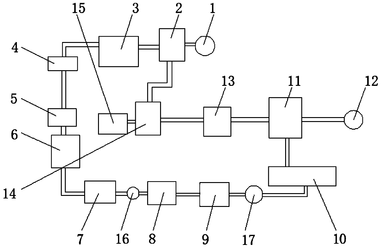
[0027] refer to Figure 1-2 , a thermal system of a 630°C double reheat unit, comprising a first generator 1, one end of the first generator 1 is fixedly connected to an ultra-high pressure cylinder 2, and one end of the ultra-high pressure cylinder 2 away from the first generator 1 is fixedly connected to a The first reheater 3, the end of the first reheater 3 away from the ultra-high pressure cylinder 2 is fixedly connected with a superheater 4, the lower end of the superheater 4 is fixedly connected with an economizer 5, and the lower end of the economizer 5 is fixedly connected with a second A high-pressure heater 6, the lower end of the first high-pressure heater 6 is fixedly connected with a second high-pressure heater 7, and the end of the second high-pressure heater 7 away from the first high-pressure heater 6 is fixedly connected with a deaerator 8, and the deaerator 8 A low-pressure heater 9 is fixedly connected to one end away from the second high-pressure heater 7,...

Embodiment 2

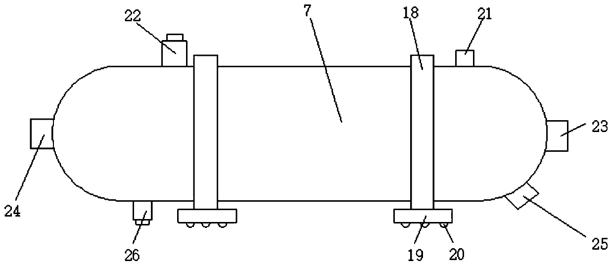
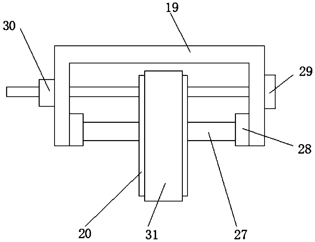
[0035] refer to Figure 1-4 , a thermal system of a 630°C double reheat unit, comprising a first generator 1, one end of the first generator 1 is fixedly connected to an ultra-high pressure cylinder 2, and one end of the ultra-high pressure cylinder 2 away from the first generator 1 is fixedly connected to a The first reheater 3, the end of the first reheater 3 away from the ultra-high pressure cylinder 2 is fixedly connected with a superheater 4, the lower end of the superheater 4 is fixedly connected with an economizer 5, and the lower end of the economizer 5 is fixedly connected with a second A high-pressure heater 6, the lower end of the first high-pressure heater 6 is fixedly connected with a second high-pressure heater 7, and the end of the second high-pressure heater 7 away from the first high-pressure heater 6 is fixedly connected with a deaerator 8, and the deaerator 8 A low-pressure heater 9 is fixedly connected to one end away from the second high-pressure heater 7,...


PUM


Abstract

The invention discloses a 630 DEG C secondary reheating unit thermodynamic system. The system includes a first generator, wherein one end of the first power generator is fixedly connected with an ultrahigh pressure cylinder, an end, away from the first generator, of the ultrahigh pressure cylinder is fixedly connected with a first reheater, an end, away from the ultrahigh pressure cylinder, of thefirst reheater is fixedly connected with a superheater, a lower end of the superheater is fixedly connected with a coal economizer, a lower end of the coal economizer is fixedly connected with a first high-pressure heater, a lower end of the first high-pressure heater is fixedly connected with a second high-pressure heater, and an end, away from the first high-pressure heater, of the second high-pressure heater is fixedly connected with a deaerator. The system is advantaged in that the thermal effect can be greatly improved, so the excessive increase of the occupied area and height of a boiler is avoided, infrastructure investment is reduced, cost is reduced, and a thermal efficiency ratio of a thermal system is optimized.

Description

technical field [0001] The invention relates to the technical field of a double reheat unit, in particular to a thermal system of a 630°C double reheat unit. Background technique [0002] The double-reheat supercritical unit has been put into operation in China for nearly four years. The power generation efficiency has reached more than 48%, and the coal consumption rate of power generation has set a world record level. It has contributed to energy conservation and emission reduction and has become a research hotspot. For high-parameter double-reheat steam turbine units, due to the situation of my country's energy revolution and energy development, it is necessary to have efficient and fast peak-shaving capabilities and flexibility to ensure the growing capacity of new energy consumption, and then realize the entire society. Clean and efficient with energy. The domestic and foreign operating experience of the double reheat unit shows that due to the addition of a reheat syst...

Claims


Application Information

Patent Timeline
IPC IPC(8): F01K7/02F01K11/00F01K3/18F22D1/32F22D1/50F16M3/00
CPCF01K3/18F01K7/02F01K11/00F16M3/00F22D1/32F22D1/50
Inventor 于海义王海旭宋远祥
Owner 大唐郓城发电有限公司
Learn More