Movable efficient waste gas burner

A waste gas combustion and mobile technology, applied in the combustion method, combustion type, lighting and heating equipment, etc., can solve the problems of changing the production process, insufficient combustion, prolonging the time interval, etc., and achieve the effect of increasing the working temperature

Inactive Publication Date: 2020-04-14
马鞍山领瞻机械科技有限公司
View PDF4 Cites 0 Cited by
  • Summary
  • Abstract
  • Description
  • Claims
  • Application Information

AI Technical Summary

Problems solved by technology

Most of the coking enterprises are open-pit coal plants. There is a lot of rainfall in summer and the rain lasts for a long time. The moisture content in the coal is easy to exceed the standard. The air humidity in the rainy season will continue to be greater than 90%. There are certain requirements, but currently coking enterprises are unable to change the production process in order to meet the operating conditions of the smoke and dust removal vehicles, so changing the structure and configuration of the smoke and dust removal vehicles has become an important goal for the production of smoke and dust removal vehicles
[0003] In addition, the smoke and dust removal vehicle and the coke oven coal charging run synchronously. Usually, the time interval between two adjacent coal charging processes is 10-30 minutes. Due to human or mechanical reasons in the coke pushing and coal charging operations, the time interval will be extended
During the waiting process, the temperature of the combustion chamber of the smoke elimination and dust removal vehicle will drop rapidly, which makes it difficult to burn the raw gas that initially enters the combustion chamber of the smoke elimination and dust removal vehicle when recharging coal. Even if it is burned, it cannot be fully burned, and black smoke will appear for a long time or mixed smoke

Method used


Image

  • Movable efficient waste gas burner
  • Movable efficient waste gas burner
  • Movable efficient waste gas burner

Examples


Embodiment 1

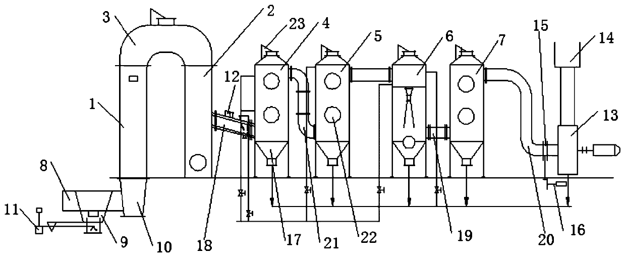
[0078] figure 1 A schematic diagram of smoke and dust removal according to an exemplary embodiment of the present invention is shown.

[0079] Such as figure 1 As shown, a mobile high-efficiency exhaust gas burner of the present invention includes: a first combustion chamber 1 connected in sequence, a combustion chamber filter section 3, a second combustion chamber 2, a dust collector, a water separator 7 and a fan 13, wherein ,

[0080] The combustion-supporting system 10 is arranged at the lower part of the first combustion chamber 1, and the first combustion chamber 1, the second combustion chamber 2 and the filter section 3 of the combustion chamber form an inverted "U" shape;

[0081] The combustion-supporting system 10 is connected with the combustion guide sleeve system 8;

[0082] The combustion guide sleeve system 8 cooperates with the guide system 9, and drives the guide system 9 to move up and down through the electric push rod 11;

[0083] The second combustion...


PUM


Abstract

The invention discloses a movable efficient waste gas burner. The burner comprises a combustion-supporting system arranged at a lower part of a first combustion chamber, wherein the first combustion chamber, a second combustion chamber and a combustion chamber filtering section form an inverted U shape, the combustion-supporting system is connected with a combustion guide sleeve system, the combustion guide sleeve system is matched with a guide system and drives the guide system to move up and down through an electric push rod, the second combustion chamber is connected with a dust remover through a first connecting pipe, a cooler is arranged on the first connecting pipe, the dust remover is connected with a water separator through a second connecting pipe, the water separator is connectedto a draught fan through a third connecting pipe, an air inlet system is arranged on the third connecting pipe, and an adjusting door is arranged below the air inlet system. A drainage system is arranged below the dust remover, an explosion-proof device is arranged above the dust remover and the water separator, and an emptying pipe is connected above the fan. The burner is advantaged in that theconstant temperature of the combustion chamber is kept, and the coal gas in various states can be fully combusted.

Description

technical field [0001] The invention relates to the technical field of coke oven coking equipment, and more specifically, to a mobile high-efficiency waste gas burner. Background technique [0002] At present, as the country has raised the requirements for pollutant discharge, the concept of environmental protection has become the core of the operation of coking enterprises. Among them, the smoke and dust removal vehicle is the auxiliary equipment for coking production. Most of the coking enterprises are open-pit coal plants. There is a lot of rainfall in summer and the rain lasts for a long time. The moisture content in the coal is easy to exceed the standard. The air humidity in the rainy season will continue to be greater than 90%. There are certain requirements, but currently coking enterprises cannot change the production process in order to meet the operating conditions of the smoke elimination and dust removal vehicles, so changing the structure and configuration of t...

Claims


Application Information

Patent Timeline
IPC IPC(8): F23G7/06F23G5/50F23J15/02
CPCF23G5/50F23G7/06F23J15/025
Inventor 孙英辉
Owner 马鞍山领瞻机械科技有限公司
Why Eureka
Try Eureka