Supercharge Your Innovation With Domain-Expert AI Agents!

Clock buffer

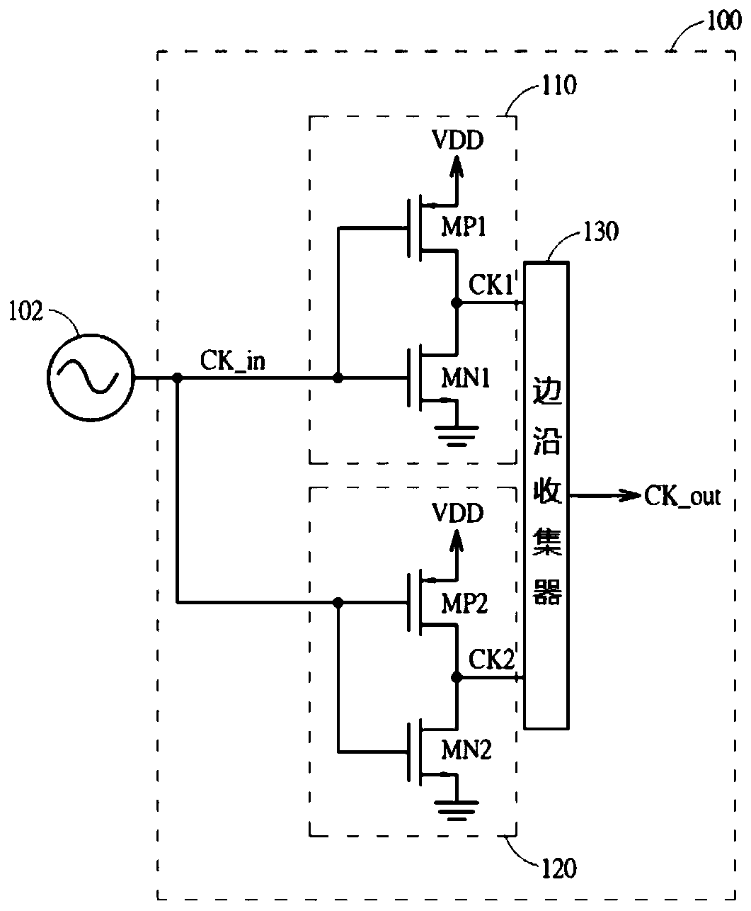
A clock buffer, input clock technology, applied in the direction of power reduction through control/clock signal, pulse technology, pulse processing, etc. Effects of low power consumption, small drift and phase noise

Pending Publication Date: 2020-04-14
MEDIATEK INC
View PDF8 Cites 0 Cited by
  • Summary
  • Abstract
  • Description
  • Claims
  • Application Information

AI Technical Summary

Problems solved by technology

However, due to the rise / fall time, both NMOS and PMOS are turned on for a long time, the quiescent current generated during this duration may dominate the power consumption of the clock signal and generate spurs to affect other circuits, where if NMOS and PMOS With larger size, more quiescent current
In order to solve this problem, U.S. Patent US8,427,209 provides a delay circuit in front of the PMOS to control the conduction period of the PMOS to reduce power consumption. However, this method will shorten the duty cycle of the output clock signal, and the edges of the output clock signal may drift to worsen the phase noise

Method used


Image

  • Clock buffer
  • Clock buffer
  • Clock buffer

Examples


Embodiment Construction

[0016] Certain terms are used in the description and claims to refer to particular components. Those skilled in the art should understand that hardware manufacturers may use different terms to refer to the same component. The specification and claims do not use the difference in name as a way to distinguish components, but use the difference in function of components as a criterion for distinguishing. "Includes" and "comprises" mentioned throughout the description and claims are open-ended terms, so they should be interpreted as "including but not limited to". "Substantially" means that within an acceptable error range, those skilled in the art can solve the technical problem within a certain error range and basically achieve the technical effect. In addition, the term "coupled" includes any direct and indirect electrical connection means. Therefore, if it is described that a first device is coupled to a second device, it means that the first device may be directly electrica...


PUM


Abstract

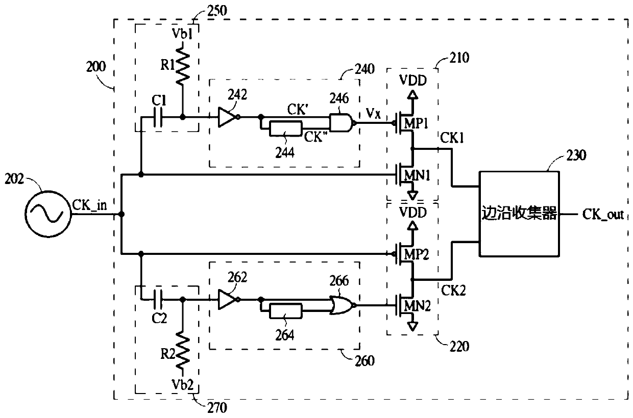
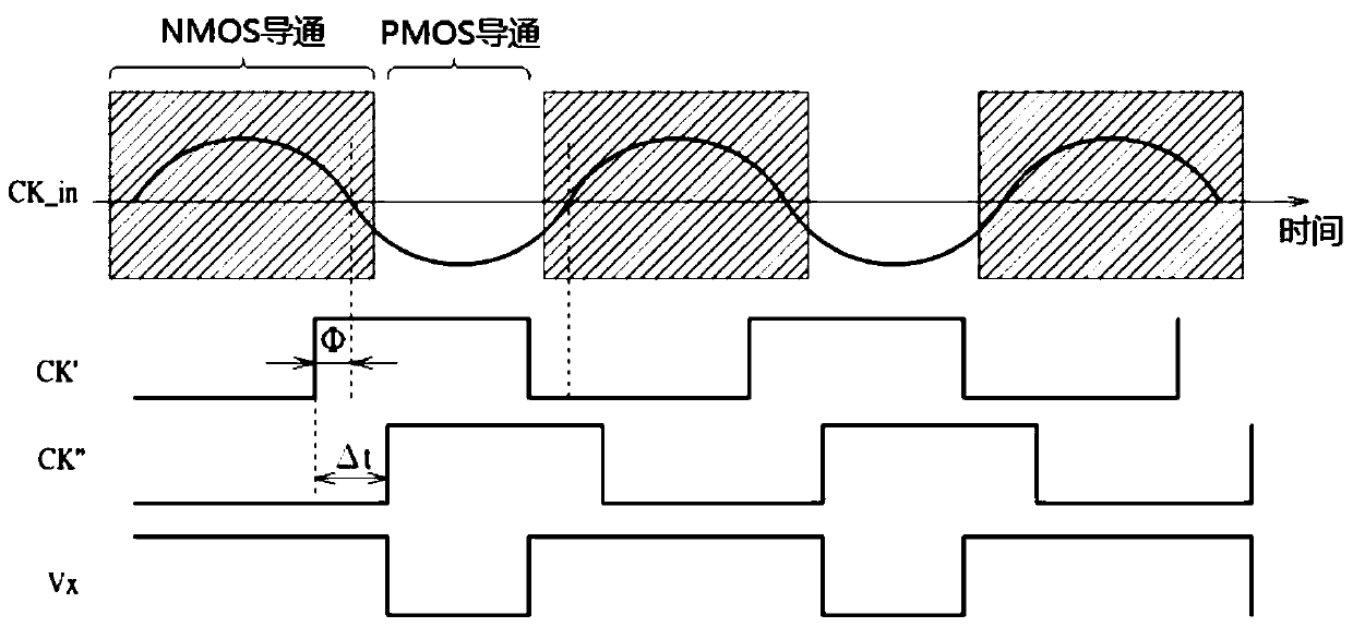
The present invention provides a clock buffer including a first circuit, a second circuit and an edge collector, wherein the first circuit is arranged to receive an input clock signal to generate a first clock signal, the second circuit is arranged to receive the input clock signal to generate a second clock signal, and the edge collector is arranged to generate an output clock signal by using a falling edge of the first clock signal and a rising edge of the second clock signal.

Description

technical field [0001] The present invention relates to the technical field of clock generation, and more particularly, to clock buffers. Background technique [0002] A traditional clock buffer is usually implemented by an inverter, and its N-type metal oxide semiconductor (NMOS) and P-type metal oxide semiconductor (PMOS) are usually designed to be larger to obtain better noise performance. However, due to the rise / fall time, both NMOS and PMOS are turned on for a long time, the quiescent current generated during this duration may dominate the power consumption of the clock signal and generate spurs to affect other circuits, where if NMOS and PMOS With larger size, the quiescent current is higher. In order to solve this problem, U.S. Patent US8,427,209 provides a delay circuit in front of the PMOS to control the conduction period of the PMOS to reduce power consumption. However, this method will shorten the duty cycle of the output clock signal, And the edges of the outp...

Claims


Application Information

Patent Timeline
IPC IPC(8): H03K19/0175H03K19/0185H03K19/00H03K19/003
CPCH03K19/017545H03K19/018557H03K19/0013H03K19/0016H03K19/00315H03K19/00361H03K5/1565G06F1/06H03K17/687H03K19/20
Inventor 陈建玮薛育理
Owner MEDIATEK INC
Features
  • R&D
  • Intellectual Property
  • Life Sciences
  • Materials
  • Tech Scout
  • Unparalleled Data Quality
  • Higher Quality Content
  • 60% Fewer Hallucinations
Learn More