Continuous production method of voltage sectional type glass-based buried optical waveguide

A production method and segmented technology, applied in the direction of optical waveguide light guide, light guide, optics, etc., can solve the problems of difficult performance optimization, limited capacity, and limited production efficiency of optical waveguide chips, so as to reduce investment in fixed assets and improve production efficiency , improve the effect of consistency

Active Publication Date: 2020-04-17
浙江大学绍兴微电子研究中心 +2
View PDF6 Cites 1 Cited by
  • Summary
  • Abstract
  • Description
  • Claims
  • Application Information

AI Technical Summary

Problems solved by technology

First of all, the capacity of the general box-type high-temperature furnace 1 is limited. Considering the temperature inhomogeneity inside the chamber of the box-type high-temperature furnace 1, the number of glass substrates that the high-temperature furnace can accommodate is affected, which limits the production efficiency and also Increased the average power consumption of the chip
Second, large-scale production requires many box-type high-temperature furnaces to work at the same time. The temperature difference between high-temperature furnaces, as well as the operator's operating speed and operating habits increase the distribution range of the optical parameters of the glass-based optical waveguide. , making it more difficult to optimize the performance of optical waveguide chips
The existing electric field-assisted ion migration technology based on box-type high-temperature furnace 1 is not suitable for large-scale and batch production of glass-based optical waveguide chips
Third, due to the Joule heating effect, only a low voltage can be applied to the glass substrate during the electric field-assisted ion diffusion process, and it takes longer to obtain the required optical waveguide burial depth, which limits the yield of optical waveguide chips

Method used


Image

  • Continuous production method of voltage sectional type glass-based buried optical waveguide
  • Continuous production method of voltage sectional type glass-based buried optical waveguide
  • Continuous production method of voltage sectional type glass-based buried optical waveguide

Examples


Embodiment 1

[0024] Embodiment 1: The continuous production method of the glass-based buried optical waveguide of the voltage segment type makes Ag + Doped glass-based buried single-mode optical waveguide

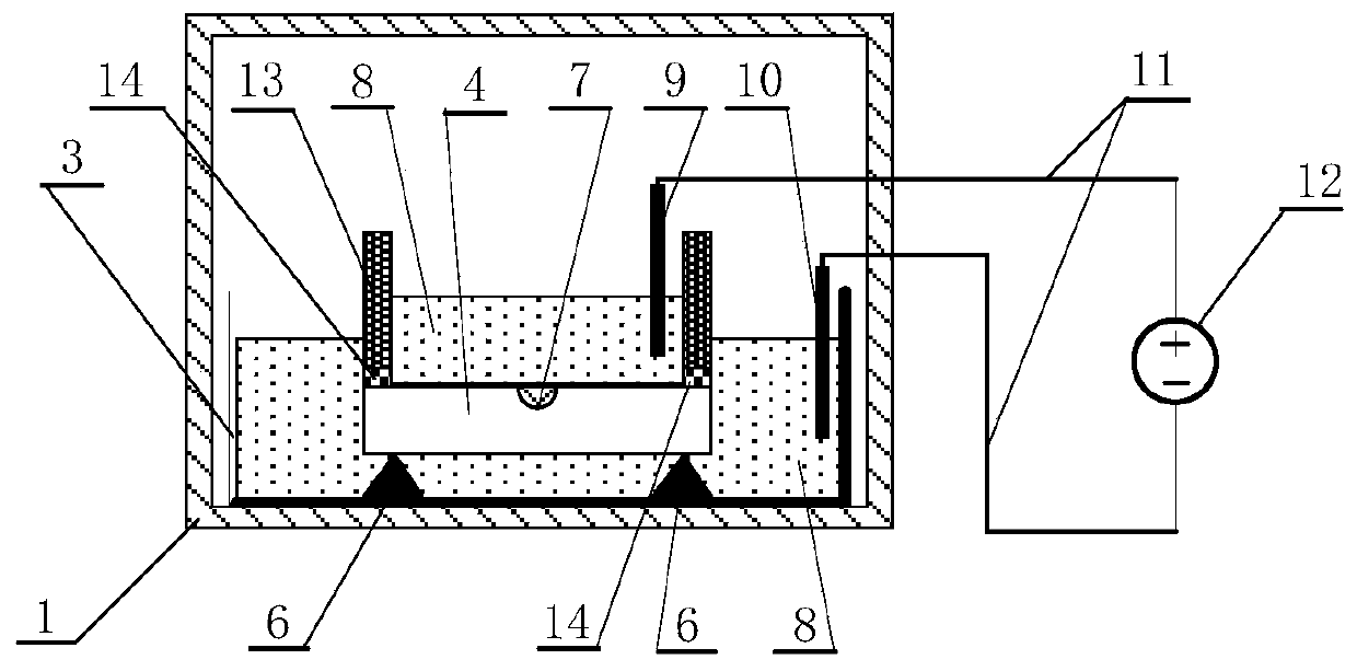
[0025] Required equipment: a tunnel-type high-temperature furnace 15 with a length of 6.0 meters, a conveyor belt 16, and a drive mechanism 17, consisting of a first positive electrode slide rail 181 with a length of 1.5 meters and a second positive electrode slide rail with a length of 2.0 meters 182. A positive electrode sliding rod and a negative electrode sliding rail 19 formed by sequentially connecting the third section of the positive electrode sliding rail 183 with a length of 3.0 meters, and the insulative sliding rail joint 22. Wherein the drive mechanism 17 can realize stepless speed change.

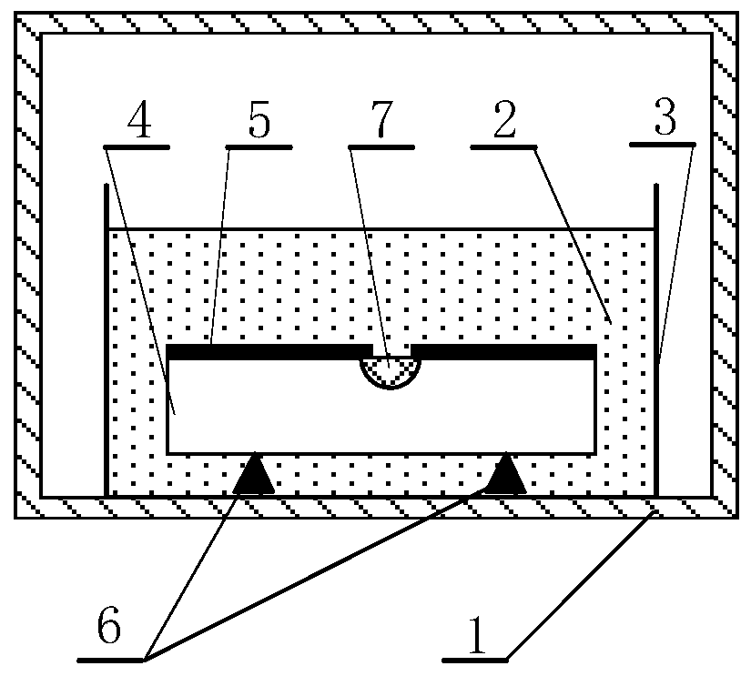
[0026] Molten salt 8 without dopant ions, here Ca(NO 3 ) 2 with NaNO 3 The mixed molten salt, the mol ratio of the two is 20:80.

[0027] by Ag + / Na + The surface waveguide sili...

Embodiment 2

[0037] Embodiment 2: The continuous production method of voltage segmented glass-based buried optical waveguide to make Ag + Doped glass-based buried multimode optical waveguide

[0038] Required equipment: a tunnel-type high-temperature furnace 15 with a length of 6.0 meters, a conveyor belt 16, and a drive mechanism 17, consisting of a first positive electrode slide rail 181 with a length of 1.5 meters and a second positive electrode slide rail with a length of 2.0 meters 182. A positive electrode sliding rod and a negative electrode sliding rail 19 formed by sequentially connecting the third section of the positive electrode sliding rail 183 with a length of 3.0 meters, and the insulative sliding rail joint 22. Wherein the drive mechanism 17 can realize stepless speed change.

[0039] Molten salt 8 without dopant ions, here Ca(NO 3 ) 2 with NaNO 3 The mixed molten salt, the mol ratio of the two is 20:80.

[0040] by Ag + / Na + The surface waveguide silicate glass sub...


PUM


Abstract

The invention discloses a continuous production method of a voltage sectional type glass-based buried optical waveguide. A tunnel type high-temperature furnace is placed, a conveying belt and a crucible are arranged in the tunnel type high-temperature furnace, the conveying belt conveys the crucible into the tunnel type high-temperature furnace from the inlet end of the tunnel type high-temperature furnace, and the crucible is conveyed to the outlet end of the tunnel type high-temperature furnace after a high-temperature ion migration reaction. The tunnel type high-temperature furnace is provided with a plurality of sections of positive electrode sliding rails connected through insulating sliding rail connectors to form a positive electrode sliding rod and a negative electrode sliding rail. In the process in which the crucible is transported from the inlet end to the outlet end of the tunnel type high-temperature furnace, electrode leads on the two sides of a glass substrate slide on the positive electrode sliding rod and the negative electrode sliding rail respectively, and the multiple sections of positive electrode sliding rails can apply a voltage to the glass substrate in sequence. On the basis of improving the quality of an optical waveguide chip, improving the production efficiency and reducing the energy consumption, the adverse effect caused by the joule heat effect generated by a direct-current electric field in the manufacturing process of the buried optical waveguide can be reduced.

Description

technical field [0001] The invention relates to the fields of optical devices and integrated optics, in particular to a continuous production method of a voltage segmented glass-based buried optical waveguide. Background technique [0002] In 1969, S.E.Miller proposed the concept of integrated optics. The basic idea is to make optical waveguides on the surface of the same substrate (or substrate), and based on this, realize the integration of various devices such as light sources, couplers, and filters. Integrated production. Through this integration, the miniaturization, weight reduction, and stabilization of the optical system can be realized, and the performance of the device can be improved. [0003] The integrated optical devices fabricated on glass substrates by ion exchange method have always been valued by business circles and researchers. Glass-based integrated optical waveguide devices based on ion exchange technology have some excellent properties, including: lo...

Claims


Application Information

Patent Timeline
Patent Type & Authority Applications(China)
IPC IPC(8): G02B6/13G02B6/12G02B6/122
CPCG02B6/12G02B6/122G02B6/13G02B2006/12038G02B2006/12085G02B2006/12166
Inventor 郝寅雷邓鑫宸蒋建光牛梦华车录锋李宇波余辉杨建义
Owner 浙江大学绍兴微电子研究中心
Why Eureka
Try Eureka