
A method for controlling the linear operating point of the bias voltage of an electro-optic modulator

An electro-optical modulator, linear operating point technology, applied in nonlinear optics, instruments, optics, etc., can solve the problems of inability to automatically find the operating point, cumbersome control process, and control accuracy easily affected by the power of the light source, etc. The effect of controlling efficiency

Active Publication Date: 2021-05-14
TIANJIN UNIV
View PDF5 Cites 0 Cited by
  • Summary
  • Abstract
  • Description
  • Claims
  • Application Information

AI Technical Summary

Problems solved by technology

The disadvantage of directly measuring optical power is that the control accuracy is easily affected by the power of the light source, and the input optical power cannot be changed arbitrarily.
The second harmonic detection method is to determine the position of the operating point by detecting the relationship between the second harmonic and the first harmonic of the modulation signal output by the electro-optic modulator. This scheme requires the use of a frequency multiplier, and the structure is relatively complicated.
Such a method cannot automatically find the working point, and the control process is cumbersome

Method used


Image

  • A method for controlling the linear operating point of the bias voltage of an electro-optic modulator
  • A method for controlling the linear operating point of the bias voltage of an electro-optic modulator
  • A method for controlling the linear operating point of the bias voltage of an electro-optic modulator

Examples


Embodiment Construction

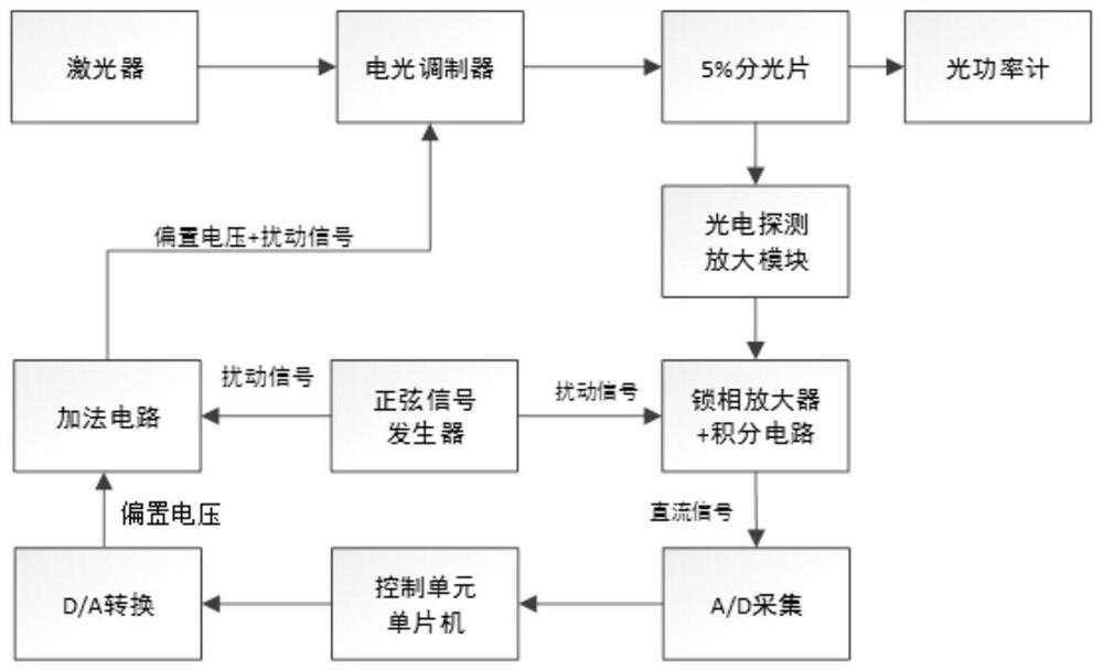
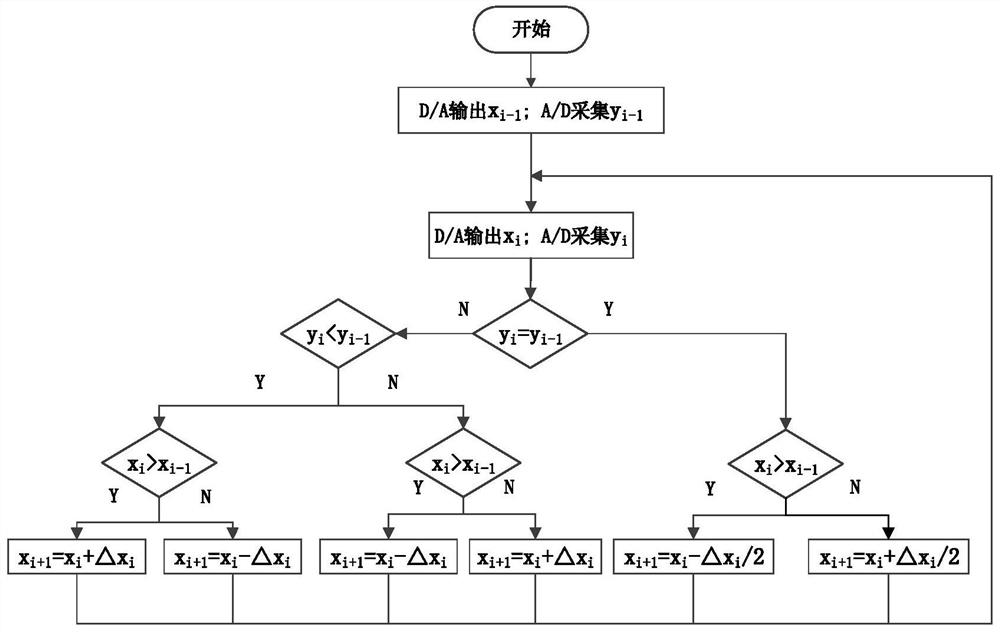
[0023] This scheme is based on the bias voltage control system of the electro-optic modulator, and uses the variable step size disturbance observation algorithm to automatically control the bias voltage.

[0024] The electro-optic modulator bias voltage control device is a closed-loop structure, including a laser, an electro-optic modulator (such as the Mach-Zehnder electro-optic intensity modulator MXAN-LN-10 of iXblue), a 5% beam splitter, and a photodetection amplifier module (such as Beijing Photodetector PDS443-C-CPIN), sinusoidal signal generator (such as AD9833), lock-in amplifier (such as AD630), integrating circuit, A / D acquisition module (such as ADS1259), control Unit microcontroller (such as STM32F103), D / A conversion module (such as DAC8563), adding circuit, optical power meter (such as Thorlabs' optical power meter set PM122D).

[0025] The present invention will be further described below in conjunction with the accompanying drawings.

[0026] The structure of ...


PUM


Abstract

The invention relates to a method for controlling the linear operating point of the bias voltage of an electro-optic modulator. The control system adopted is a closed-loop system, including a laser, an electro-optic modulator, a 5% beam splitter, a photoelectric detection amplification module, a sinusoidal signal generator, and a phase-locked Amplifier, integrating circuit, A / D acquisition module, control unit microcontroller, D / A conversion module, adding circuit, optical power meter, track and control the output bias voltage by judging the DC voltage gradient collected by A / D, and then Make the operating point stable at the linear operating point to stabilize the operating point.

Description

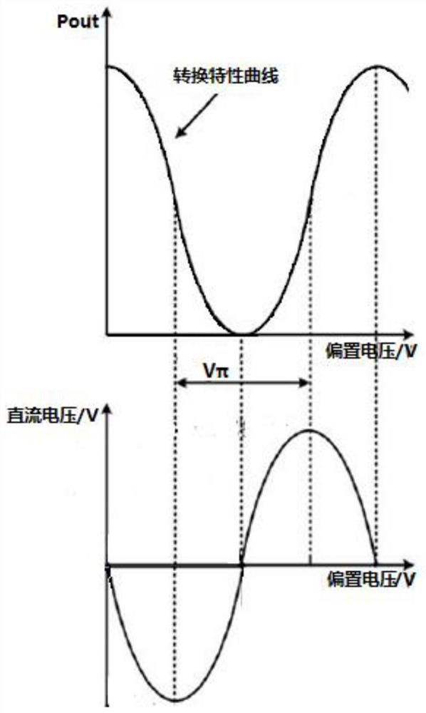
technical field [0001] The invention relates to the field of electro-optic modulators, in particular to an automatic control algorithm for the linear operating point of the bias voltage of the electro-optic modulator. Background technique [0002] Electro-optic modulators are more and more widely used in the field of microwave photonics. For example, light-borne microwave ranging uses microwaves to modulate light waves, and the modulated waves are used as measurement signals. This process requires the use of electro-optic modulators. In the process of using the electro-optic modulator, an appropriate bias operating point is required, that is, an appropriate bias voltage is applied. When the electro-optic modulator is used for optical-borne microwave interference ranging, the operating point must be stable at the linear operating point, that is, the offset phase is π / 2. However, due to its own structural reasons, the operating point will slowly drift with mechanical vibratio...

Claims


Application Information

Patent Timeline
Patent Type & Authority Patents(China)
IPC IPC(8): G02F1/01
CPCG02F1/0123
Inventor 吴斌吉逸喆
Owner TIANJIN UNIV
Learn More