

Automatic mechanical equipment for feed stirring
A technology for mechanical equipment and feed mixing, which is applied to mixers with rotary mixing devices, mixer accessories, feed and other directions, can solve the problems that the feed does not reach the ideal feeding effect, the ratio of feed fillers is unreasonable, and the cost of use is high. To achieve the effect of reducing human intervention, facilitating absorption and improving processing efficiency
- Summary
- Abstract
- Description
- Claims
- Application Information
AI Technical Summary
Problems solved by technology
Method used
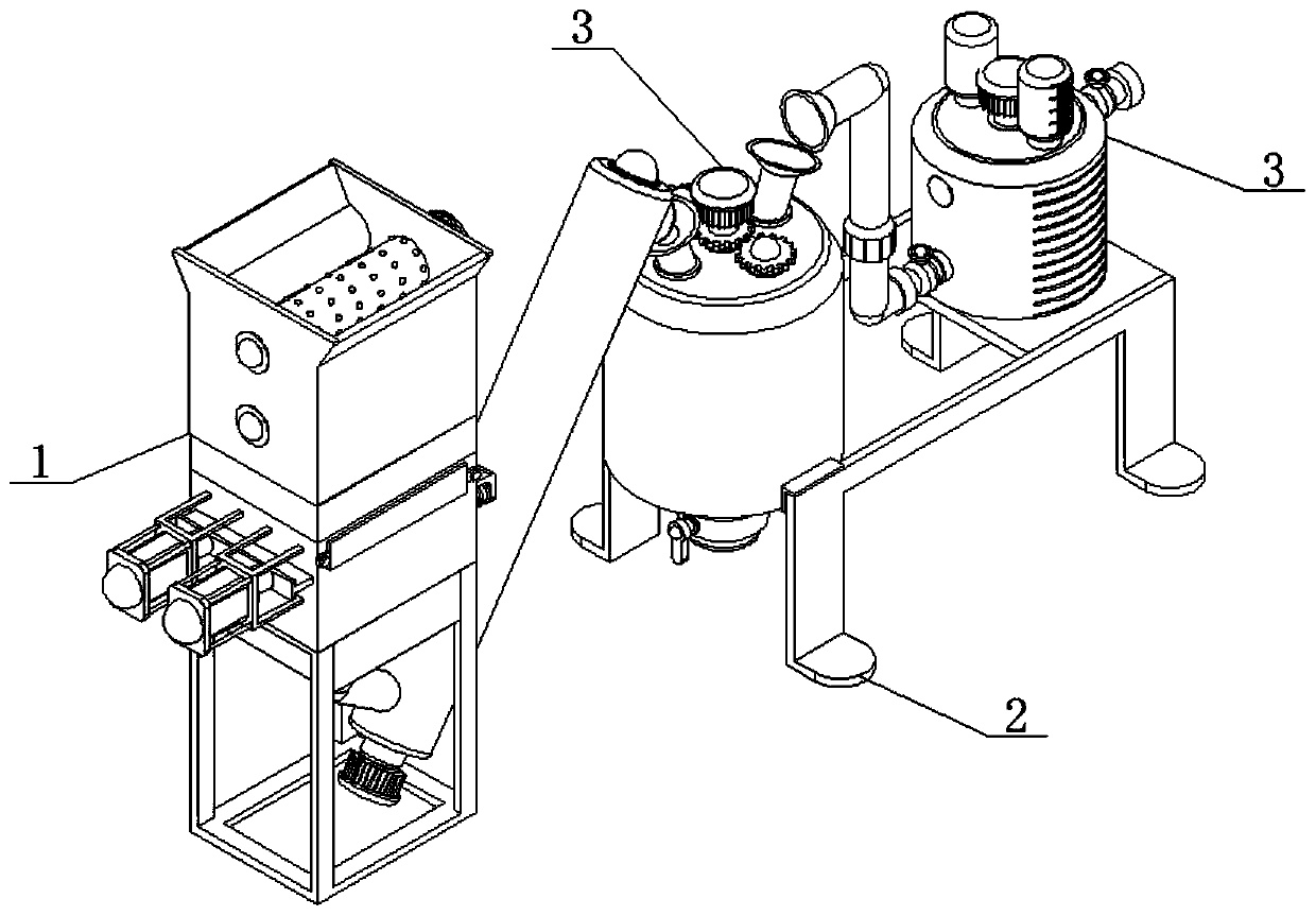
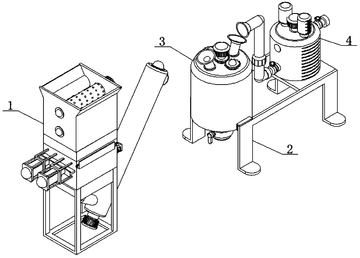
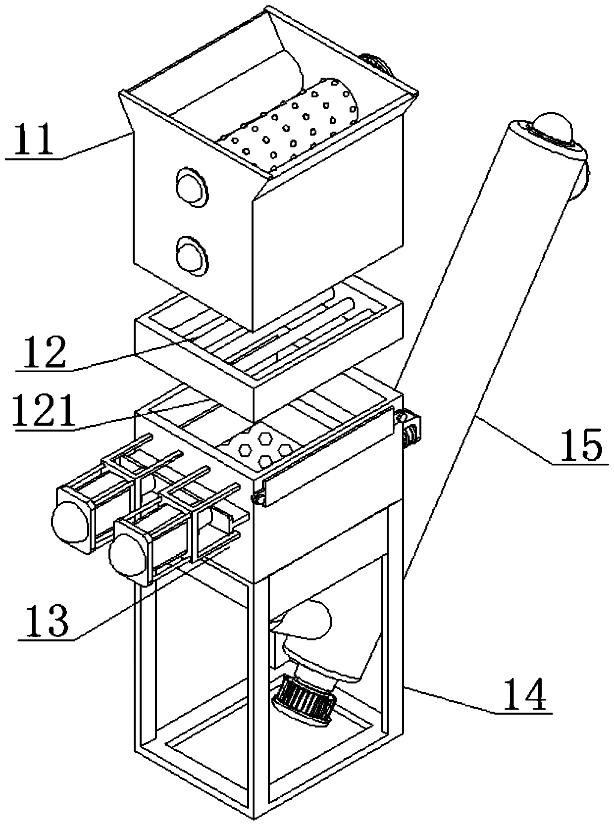
Image

Examples
Embodiment Construction
[0042] In order to make the purpose, technical solutions and advantages of the embodiments of the present invention clearer, the technical solutions in the embodiments of the present invention will be clearly and completely described below in conjunction with the accompanying drawings in the embodiments of the present invention. Obviously, the described embodiments It is some embodiments of the present invention, but not all of them. Based on the implementation manners in the present invention, all other implementation manners obtained by persons of ordinary skill in the art without creative efforts fall within the protection scope of the present invention. Accordingly, the following detailed description of the embodiments of the invention provided in the accompanying drawings is not intended to limit the scope of the claimed invention, but merely represents selected embodiments of the invention. Based on the implementation manners in the present invention, all other implement...
PUM
 Abstract
Description
Claims
Application Information