
Eureka
For R&D, Eureka makes reading and utilizing patents & technical documents easy.
Eureka AIR
Designed for self-driven R&D workflows. Generate viable solutions, solve complex R&D challenges, empower your innovation with AI.

Eureka Materials
Designed for material experts only. Revolutionize your material R&D, from search, analyze, to developing new materials.

TechResearch
Generate reliable direction feasibility study reports for your R&D in just a few steps.

TechSeek
Discover and master advanced knowledge NOW. Basics, ideas, possibilities, all at once.

TechMind
As an expert in R&D Theories, TechMind can generates customized viable solutions instantly.

TechRisk
Analyze your overall solution with one click, know your potential R&D risks in advance.

TechMonitor
Get weekly tech updates, stay abreast of the latest tech innovations and key insights.
Method and device for real-time detection and control of rotation of hollow stud welding arc
A real-time detection, stud welding technology, applied in the direction of electrode support device, cleaning method using liquid, arc welding equipment, etc., can solve the problems of non-welding, welding arc cannot be effectively rotated, etc., to achieve simple operation and improve welding success The effect of high rate and high efficiency
- Summary
- Abstract
- Description
- Claims
- Application Information
AI Technical Summary
Problems solved by technology
Method used
Image

Examples
Embodiment 1
[0034] Take the welding of a Q235 hollow stud with a diameter of 20mm at a welding current of 800A and a magnetic field current of 0.34A as an example.
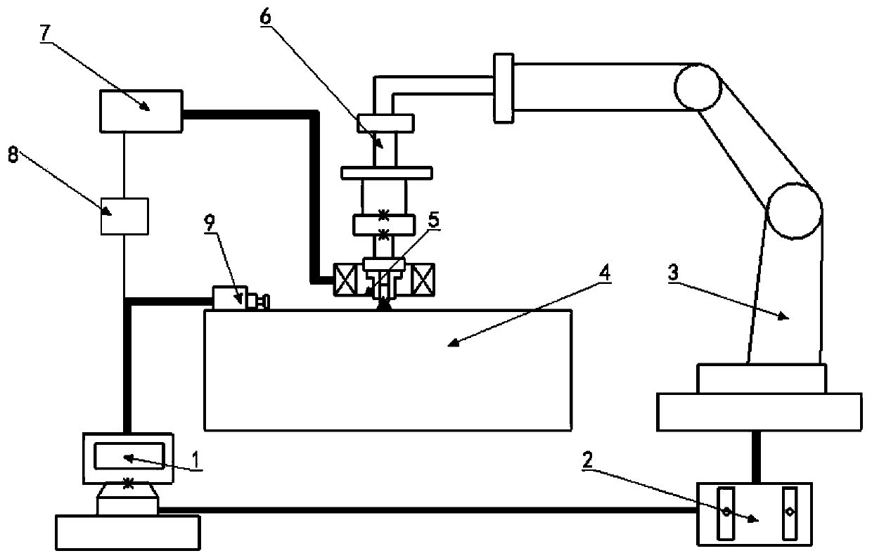
[0035] 1. Connect the stud welding robot, welding machine, magnetic field control power supply, CCD high-speed camera and computer according to the figure 2 The installation diagram shown completes the connection;
[0036] 2. Use fine sandpaper to polish the end face of the 20mm hollow stud to be welded and the base metal to be welded, and then clean it with acetone and dry it quickly;
[0037] 3. Start the automatic stud welding robot, control the robot to grip the stud to the welding position, control the welding torch to complete the preload, set the welding current to 800A, the welding time to 1450ms, the initial current of the magnetic field control power supply to 0.34A, and start the drawn arc welding torch for welding ;
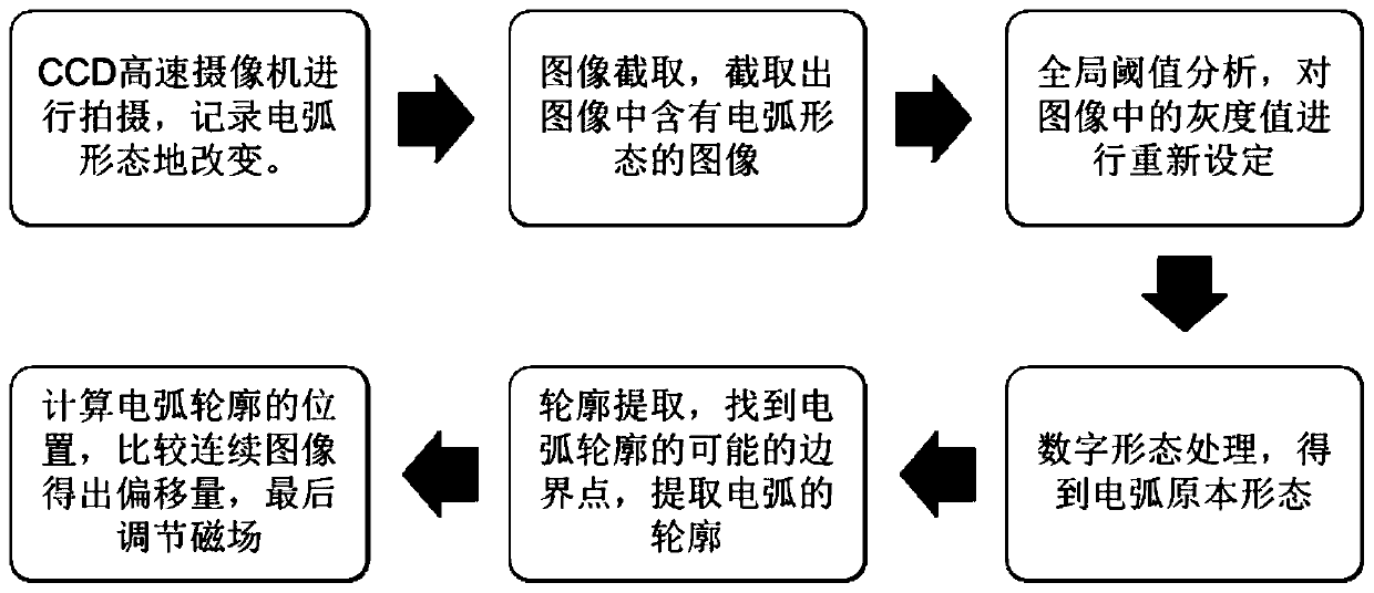
[0038] 4. During the welding process, the welding process is photographed by the CCD high-speed...
Embodiment 2
[0047] Take the welding of Q235 hollow studs with a diameter of 20mm under a magnetic field of 0.52A as an example.
[0048] 1. Connect the stud welding robot, welding machine, magnetic field control power supply, CCD high-speed camera and computer according to the figure 2 The installation diagram shown completes the connection;
[0049] 2. Grind the end face of the 20mm hollow stud and the base metal area to be welded with fine sandpaper, then clean it with acetone and dry it quickly;
[0050] 3. Start the automatic stud welding robot, control the robot to grip the stud to the welding position, control the welding torch to complete the preload, set the welding current to 900A, the welding time to 1450ms, the initial current of the magnetic field control power supply to 0.52A, and start the drawn arc welding torch for welding ;
[0051] 4. During the welding process, use the CCD high-speed camera to shoot the welding process, and set the shooting parameters of the CCD high-...
PUM
| Property | Measurement | Unit |
|---|---|---|
| Shear strength | aaaaa | aaaaa |
| Shear strength | aaaaa | aaaaa |
| Shear strength | aaaaa | aaaaa |
Abstract
Description
Claims
Application Information
 - R&D Engineer
- R&D Manager
- IP Professional
- Industry Leading Data Capabilities
- Powerful AI technology
- Patent DNA Extraction
Browse by: Latest US Patents, China's latest patents, Technical Efficacy Thesaurus, Application Domain, Technology Topic, Popular Technical Reports.
© 2024 PatSnap. All rights reserved.Legal|Privacy policy|Modern Slavery Act Transparency Statement|Sitemap|About US| Contact US: help@patsnap.com