Production equipment of polyester fiber reinforced strip

A technology of polyester fiber and production equipment, applied in the field of polyester fiber processing, can solve the problems of increasing the molecular force between the mixture and the strip roll, increasing the melt index of polyethylene resin, etc., so as to improve the contact smoothness and reduce the coverage. , the effect of preventing backflow

Inactive Publication Date: 2020-04-28
林国盛
View PDF0 Cites 0 Cited by
  • Summary
  • Abstract
  • Description
  • Claims
  • Application Information

AI Technical Summary

Problems solved by technology

[0003] The main material of the reinforced strip in the production process is a mixture of polyethylene resin and polyester fiber. The mixing of the two needs to be carried out under heating conditions, while the strip roller used in the prior art is used for extrusion coating A

Method used


Image

  • Production equipment of polyester fiber reinforced strip
  • Production equipment of polyester fiber reinforced strip
  • Production equipment of polyester fiber reinforced strip

Examples


Example Embodiment

[0026] Example 1

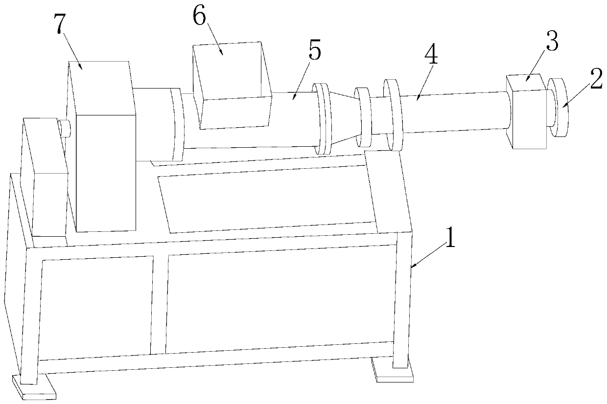
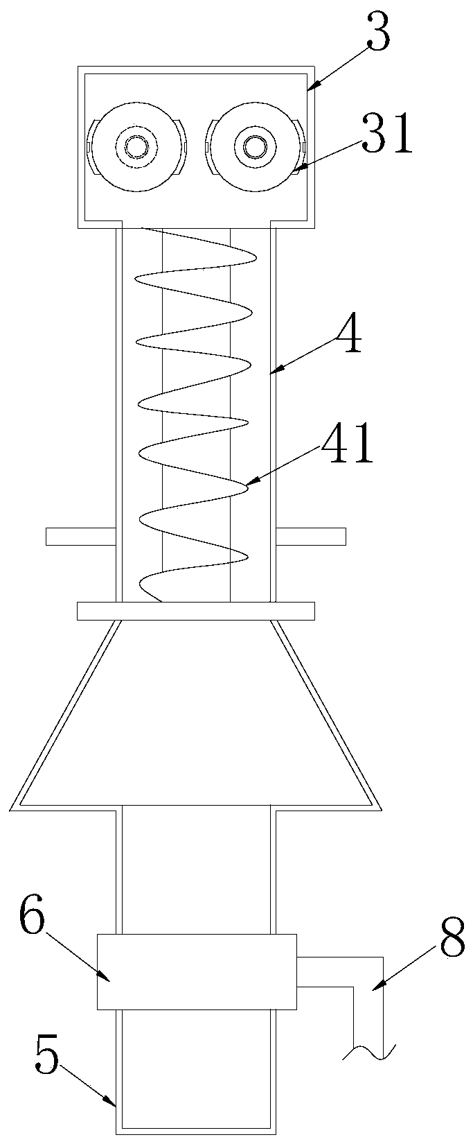
[0027] Such as figure 1 , figure 2 , Figure 4 , Figure 5 As shown, the present invention provides a production equipment for polyester fiber reinforced strips, the structure of which includes a chassis 1, an extrusion port 2, a coating port 3, an extrusion cavity 4, a mixing barrel 5, a polyethylene addition port 6, a deceleration 7, polyester fiber adding port 8, the case 1 controls the reducer 7, the signal output end of the reducer 7 is electrically connected to the extrusion cavity 5, and the extrusion cavity 5 is provided with an extrusion Screw 41, the extrusion cavity 5 is provided with a polyethylene addition port 6 and a polyester fiber addition port 8, the mixing barrel 5 is in horizontal communication with the interior of the extrusion cavity 4, and the extrusion cavity 4 is opposite to the mixing barrel 5. An extrusion port 2 and a coating port 3 are installed at one end of the coating port 3. The coating port 3 is provided with a strip roller 31...

Example Embodiment

[0028] Example 2

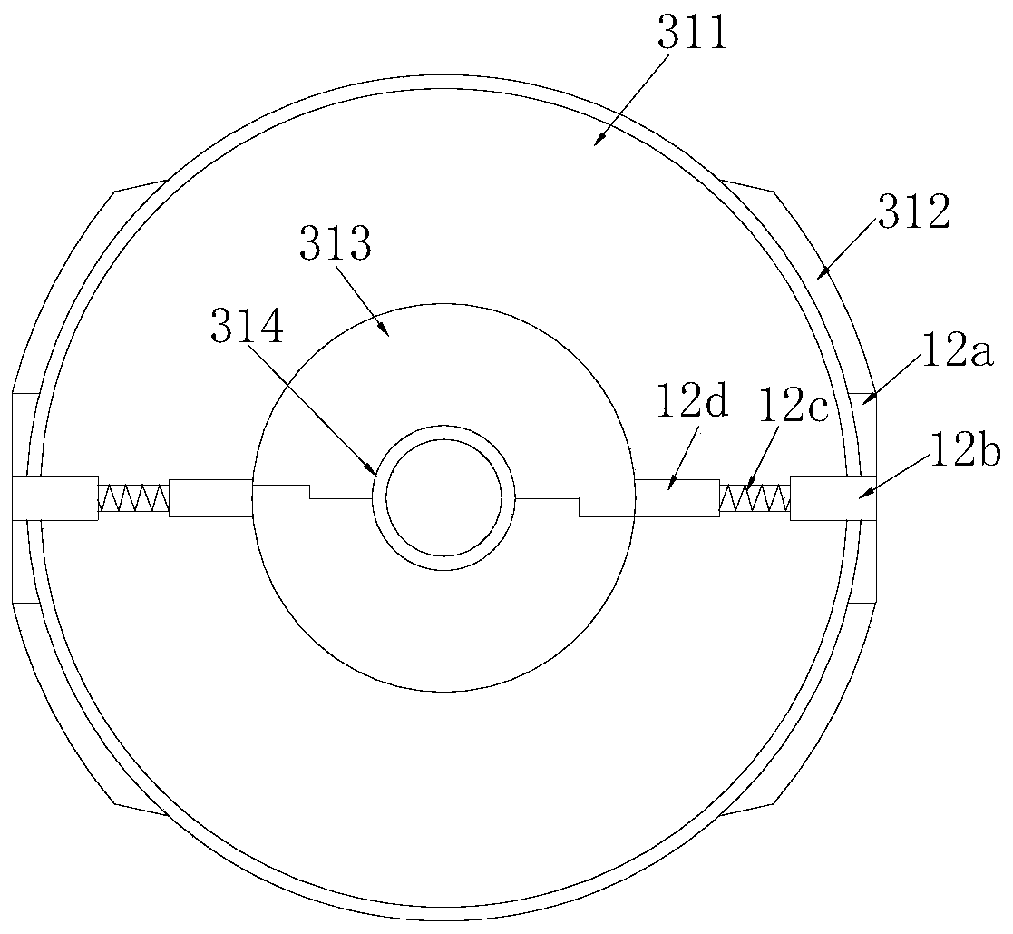
[0029] Based on the description in Example 1, as image 3 versus Image 6 As shown, the tangent disc 312 has an arc shape that fits the roller surface 311, and both sides are inclined tangent structures. The gap between the roller surface 311 and the liquid outlet 12a is provided with a pore a. a. There are more than two and are evenly distributed in the circumferential direction. The liquid collection tank 313 is divided into two equal parts, and is Z-shaped at each slit. The roller surface 311 has a stepped double-layer structure. The contact between the layers is inclined to increase the oil outflow rate in the pore a. The sump 313 is divided into two equal parts, and the zigzag-shaped incision can well divide the lubricant into each outlet channel; At the same time, the roller surface 311 is a double layer, and the interlayer is inclined, which makes the pore a more comprehensive, and the lubrication efficiency of the roller surface 311 is higher. Furthermo...


PUM


Abstract

The invention discloses production equipment of a polyester fiber reinforced strip. The production equipment structurally comprises a case, an extrusion port, a coating port, an extrusion cavity, a mixing cylinder, a polyethylene adding port, a speed reducer, a polyester fiber adding port and a case control speed reducer. A signal output end of the speed reducer is electrically connected with theextrusion cavity, an extrusion screw rod is arranged in the extrusion cavity, the extrusion cavity is provided with the polyethylene adding port and the polyester fiber adding port, the mixing cylinder is in horizontal communication with the interior of the extrusion cavity, and the end, opposite to the mixing cylinder, of the extrusion cavity is provided with the extrusion port and the coating port. A liquid collecting groove is matched with a roller core and an infusion system, the roller core rotates to open a closing disc and a closing rod by utilizing centrifugal force, a top block and aconnecting rod are hollow, and lubricant is infused from the inside of the top into the connecting rod to be diffused to the whole roller surface in a fine hole so as to play a role of lubricating theroller surface, the contact smoothness between the polyethylene and polyester fiber mixture and a strip roller is improved, the mixture coverage is reduced, and better extrusion is realized.

Description

technical field [0001] The invention relates to the technical field of polyester fiber processing, in particular to a production equipment for polyester fiber reinforced strips. Background technique [0002] Polyester fiber, commonly known as "polyester", is a synthetic fiber obtained by spinning polyester obtained by polycondensation of organic dibasic acid and dibasic alcohol, referred to as PET fiber, which belongs to polymer compounds. Reinforcing strips play a vital role in retaining walls, slope protection, high fill, tailings dams, and embankments; [0003] The main material of the reinforced strip in the production process is a mixture of polyethylene resin and polyester fiber. The mixing of the two needs to be carried out under heating conditions, while the strip roller used in the prior art is used for extrusion coating At this time, because the heating increases the molecular force between the mixture and the strip roller, the melting index of the polyethylene re...

Claims


Application Information

Patent Timeline
IPC IPC(8): B29C48/08B29C48/94B29K23/00B29K67/00
CPCB29C48/08B29C48/94B29K2023/06B29K2067/003
Inventor 林国盛
Owner 林国盛
Why Eureka
Try Eureka