LPCVD double material vacuum reaction chamber

A reaction chamber, dual-material technology, applied in metal material coating process, gaseous chemical plating, coating and other directions, can solve the problems of difficulty in meeting design requirements, easy aging of sealing rings, frequent replacement of O-rings, etc. Improve the uniformity and process quality, improve the overall service life, and the effect of wide and uniform gas dispersion

Pending Publication Date: 2020-04-28
赛姆柯(苏州)智能科技有限公司
View PDF0 Cites 3 Cited by
  • Summary
  • Abstract
  • Description
  • Claims
  • Application Information

AI Technical Summary

Problems solved by technology

[0005] At this stage, the vacuum reaction chamber is a single-layer quartz tube. During the movement of pushing the boat and closing the furnace door, a certain extrusion force will be generated instantly when touching the quartz tube, and the inner wall of the quartz tube will be covered with polysilicon Cracks or damage will occur in places where single-layer quartz tubes have low service life and are cumbersome to replace; quartz material vacuum chambers have many processing procedures, the accuracy is difficult to meet the design requirements, and the time-consuming cycle is long
[0006] The existing quartz-sealing ring-metal contact, the sealing ring is easy to age at high temperature, the internal temperature of the LPCVD reaction chamber is 750°C, and the applicable temperature of the furnace mouth sealing ring (246 type fluorine rubber O-ring) is about 300-500°C , the heat exchange makes the O-rings use for a period of time, and its sealing effect gradually decreases, which has an impact on the gas reaction thin film, resulting in frequent replacement of O-rings
[0007] In addition, in the existing air intake method, there is a situation that the flow rate of the air outlet hole gradually decreases from the air intake end to the tail of the air pipe, which affects the uniformity of the silicon wafer film and the process quality

Method used


Image

  • LPCVD double material vacuum reaction chamber
  • LPCVD double material vacuum reaction chamber
  • LPCVD double material vacuum reaction chamber

Examples


Embodiment Construction

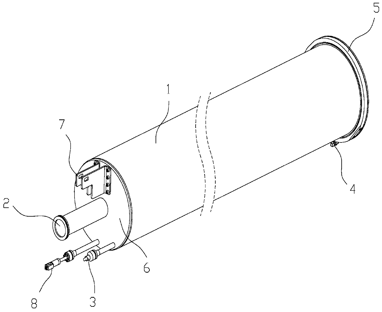
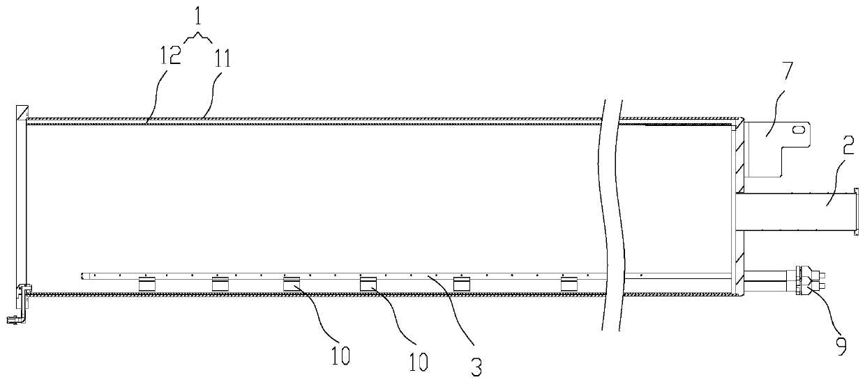
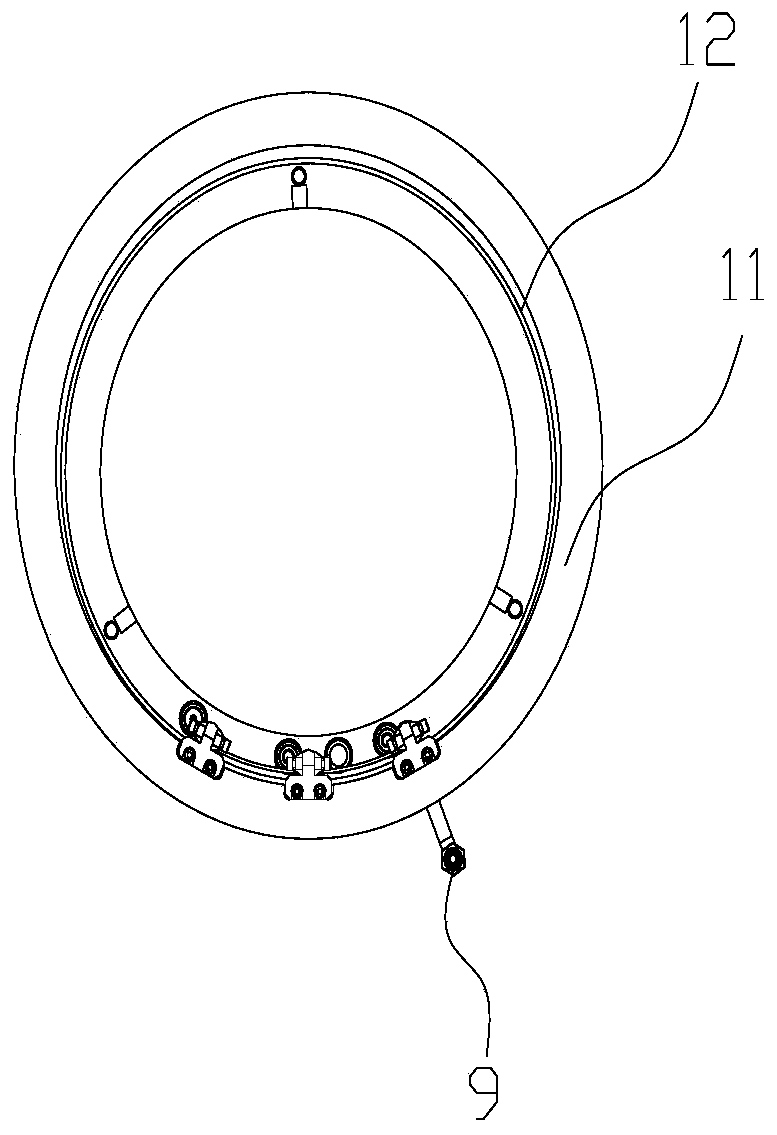
[0033] In order to enable those skilled in the art to better understand the solutions of the present invention, the following will clearly and completely describe the technical solutions in the embodiments of the present invention in conjunction with the drawings in the embodiments of the present invention. Obviously, the described embodiments are only It is an embodiment of a part of the present invention, but not all embodiments. Based on the embodiments of the present invention, all other embodiments obtained by persons of ordinary skill in the art without making creative efforts shall fall within the protection scope of the present invention.

[0034] It should be noted that the terms "first" and "second" in the description and claims of the present invention and the above drawings are used to distinguish similar objects, but not necessarily used to describe a specific sequence or sequence. It is to be understood that the data so used are interchangeable under appropriate ...


PUM


Abstract

The invention discloses an LPCVD double material vacuum reaction chamber, which comprises a reaction chamber, an air inlet assembly and an air outlet pipe; and the air inlet assembly is connected withan external air source, the reaction chamber comprises an outer cavity and an inner cavity arranged in the outer cavity, the air inlet assembly comprises one or more left air inlet pipes and one or more right air inlet pipes, an air inlet of each left air inlet pipe is arranged at the end portion of the reaction chamber in the length direction, an air inlet of each right air inlet pipe is arranged at the other end of the reaction chamber in the length direction, and a plurality of air outlets are correspondingly arranged on the left air inlet pipes and the right air inlet pipes. According tothe LPCVD double material vacuum reaction chamber, the two ends of the reaction chamber correspondingly has air inlet pipes for gas diffusion, thus gas in the reaction chamber is widely and evenly distributed, air outlet is stable, the uniformity and process quality of a silicon thin film are improved, and the excellent rate of a product is improved; the vacuum reaction chamber adopts a double-layer structure, the vacuum performance is excellent, the impact resistance is high, the strength of the overall reaction chamber is improved, and the service life is prolonged.

Description

technical field [0001] The invention relates to the field of LPCVD vacuum reaction chambers, in particular to an LPCVD double-material vacuum reaction chamber. Background technique [0002] Due to the attention paid to the development of renewable energy and the rapid promotion of solar photovoltaic power generation, as the feature size of semiconductor processes decreases, and the requirements for film uniformity and film thickness error continue to increase, LPCVD has excellent step coverage and good composition Composition and structure control, high deposition rate, and this method does not require ion-carrying gas, thus greatly reducing the source of particle pollution, and is widely used in the thin film deposition process of the semiconductor industry. [0003] LPCVD (Low Pressure Chemical Vapor Deposition, low pressure chemical vapor deposition) equipment is under the condition of low pressure and high temperature, through the chemical reaction of mixed gas to genera...

Claims


Application Information

Patent Timeline
Patent Type & Authority Applications(China)
IPC IPC(8): C23C16/455C23C16/458
CPCC23C16/45559C23C16/45561C23C16/4581
Inventor 张凤嘉任俊江薇儿妮卡·夏丽叶张灵肖益波
Owner 赛姆柯(苏州)智能科技有限公司
Why Eureka
Try Eureka