Guide cylinder device and crystal pulling furnace

A technology of guide tube and guide wall, which is applied in the field of guide tube devices and crystal pulling furnaces, can solve the problems of high integrated circuit potential impact, crystal ingot quality, etc., to avoid void defects, improve crystal ingot quality, Suppresses the effect of supersaturation

Active Publication Date: 2020-04-28
XIAN ESWIN MATERIAL TECH CO LTD +1
View PDF5 Cites 0 Cited by
  • Summary
  • Abstract
  • Description
  • Claims
  • Application Information

AI Technical Summary

Problems solved by technology

[0004] But too high v / G 0 The value will also lead to a lot of void-type defects in the ingot. These void-type defects are caused by the supersaturation of vacancies, which will affect the quality of the ingot, which will affect the potential of silicon wafers to manufacture complex high-integration circuits. have a great impact

Method used


Image

  • Guide cylinder device and crystal pulling furnace
  • Guide cylinder device and crystal pulling furnace
  • Guide cylinder device and crystal pulling furnace

Examples


Embodiment 1

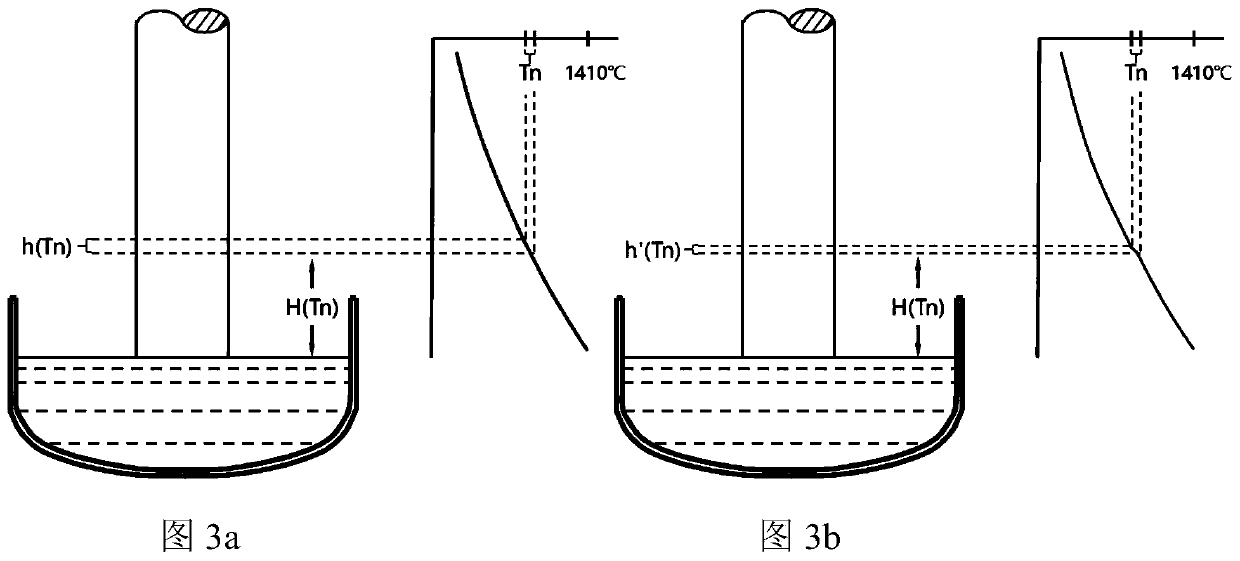
[0034] The formation of void-type defects usually goes through two processes. First, during the cooling process of the ingot, as the distance from the solid-liquid interface increases, the supersaturation of the vacancies gradually increases. When the supersaturation reaches a certain value at a certain temperature, The vacancies aggregate to nucleate and then grow through vacancy diffusion. Since the migration rate of vacancies decreases as the temperature of the ingot decreases, the characteristic temperature range Tn for the rapid nucleation and growth of void-type defects due to the aggregation reaction of vacancy-type intrinsic defects is roughly 1100-1070°C. Determines the size of the void defect. When the temperature is greater than Tn, the nucleation rate of void defects is very small; in the Tn temperature range, the nucleation rate of void defects is very high; when the ingot temperature is lower than Tn, the nucleation rate of void defects is rapid decreases, and i...

Embodiment 2

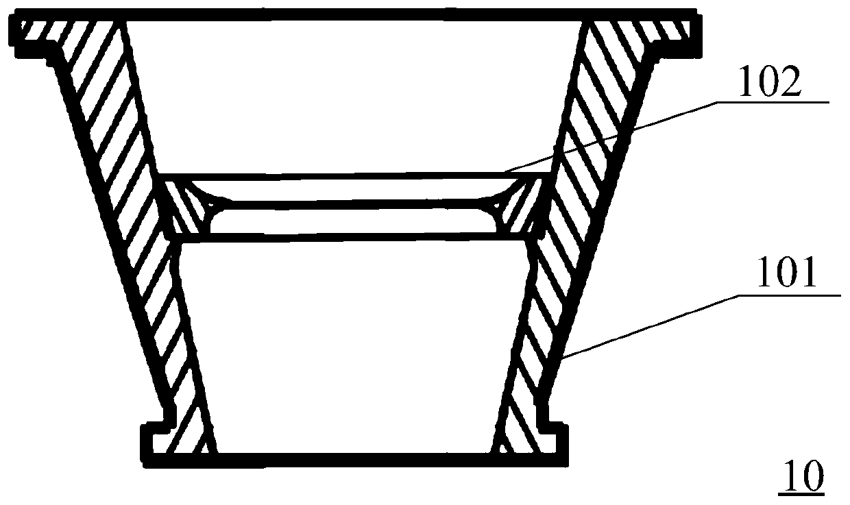
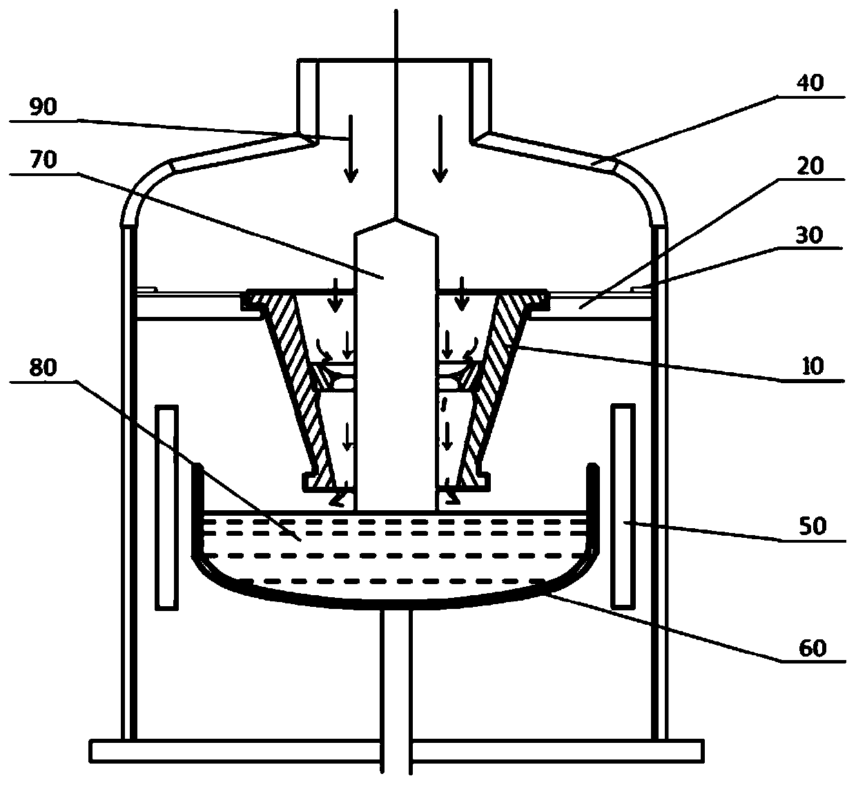
[0060] See figure 1 and figure 2 , the present embodiment also provides a crystal pulling furnace on the basis of the above embodiments, the crystal pulling furnace is used to manufacture crystal ingots 70, including: a furnace body 40, the furnace body 40 includes a draft tube device 10, a heat preservation cover 20 , pressure ring 30, heater 50, quartz crucible 60; body of furnace 40 passes inert gas 90 from top to bottom; The design enables the inert gas 90 to pass into the crystal pulling furnace from the auxiliary chamber. During the process of the inert gas 90 flowing from the ingot 70 to the melt 80, when it moves to the diameter reducing device 102 of the draft tube device 10, due to the gas flow The channel becomes smaller, so that the flow velocity of the inert gas 90 when flowing through the diameter reducing device 102 increases, so that the ingot 70 at this height can be cooled intensively.

[0061] It should be understood that the other devices of the crystal ...


PUM


Abstract

The invention relates to a guide cylinder device, which comprises a guide cylinder body and a reducing device, the guide cylinder body and the reducing device are each provided with a guide channel, the reducing device surrounds the guide cylinder body and is attached to the inner wall of the guide cylinder body, and the height of the guide wall of the reducing device is larger than or equal to the height of a to-be-cooled section of a crystal bar. The reducing device is arranged on the inner wall of the guide cylinder body; when inert gas is introduced into a crystal pulling furnace, the crystal pulling furnace is heated; when the inert gas moves to the reducing device; due to the existence of the reducing device; the airflow channel is reduced; the flow speed of the inert gas at the reducing device is increased; therefore, the crystal bars at the height can be cooled in a centralized manner; meanwhile, if the height of the reducing device coincides with the height of the characteristic temperature interval of the crystal bar, the degree of supersaturation of vacancy type intrinsic defects can be effectively restrained, and therefore the crystal bar can be effectively prevented from generating large-size cavity type defects, and finally the effect of improving the quality of the crystal bar is achieved.

Description

technical field [0001] The invention belongs to the technical field of semiconductors, and in particular relates to a draft tube device and a crystal pulling furnace. Background technique [0002] Monocrystalline silicon is now the base material for most semiconductor components, and the vast majority of monocrystalline silicon is prepared by the "Czochralski method (Czochralski method)". In this method, the polycrystalline silicon material is placed in a quartz crucible and melted. During the Czochralski single crystal process, the seed crystal is first brought into contact with the melt, so that the molten silicon at the solid-liquid interface cools and crystallizes along the seed crystal, and is slowly pulled out. After the necking is completed, the crystal growth diameter is enlarged by reducing the pulling speed and / or melt temperature until the target diameter is reached; after turning the shoulder, the crystal growth enters "equal diameter growth" by controlling the p...

Claims


Application Information

Patent Timeline
Patent Type & Authority Applications(China)
IPC IPC(8): C30B15/00C30B29/06
CPCC30B15/00C30B29/06
Inventor 杨帅军雷卫娜阴俊沛惠聪王腾
Owner XIAN ESWIN MATERIAL TECH CO LTD
Why Eureka
Try Eureka