Pneumatic forming pin shearing and coating removing integrated equipment

A technology of coating and equipment, applied in the field of integrated equipment for pneumatic forming scissors and decoating, can solve the problems of reducing work efficiency, low efficiency, and affecting base assembly, etc., and achieves reduced labor intensity, high integration, and improved overall efficiency effect

Pending Publication Date: 2020-04-28
WUHAN CHENYANG ELECTRONICS TECH
View PDF0 Cites 1 Cited by
  • Summary
  • Abstract
  • Description
  • Claims
  • Application Information

AI Technical Summary

Problems solved by technology

[0006] The purpose of the present invention is to provide a kind of integrated equipment for pneumatic forming and scissors to remove the coating, to solve the problem that the existing pins proposed in the above background technology are mainly handled manually, and the manual scissors are easy to remove the product pins. Cutting to different lengths will affect the assembly of the base, and the process of pulling the pins of the product lacks control methods, it is difficult to limit the forming, there is rebound bending, and the controllability of the cutting feet is also reduced. In the face of a large number of manual cutting The labor intensity of the feet is high, the fatigue is high, and the efficiency is low without operating experience. At the same time, due to the lack of recycling methods for waste materials, the work area is chaotic, and the sharp cut surfaces of waste materials are easy to puncture the flesh, posing safety hazards. Faced with the need to remove During the coating process, it is necessary to cooperate with the grinder for secondary treatment, which reduces the work efficiency and is not conducive to increasing the integration problem

Method used


Image

  • Pneumatic forming pin shearing and coating removing integrated equipment
  • Pneumatic forming pin shearing and coating removing integrated equipment
  • Pneumatic forming pin shearing and coating removing integrated equipment

Examples


Embodiment Construction

[0022] The following will clearly and completely describe the technical solutions in the embodiments of the present invention with reference to the accompanying drawings in the embodiments of the present invention. Obviously, the described embodiments are only some, not all, embodiments of the present invention. Based on the embodiments of the present invention, all other embodiments obtained by persons of ordinary skill in the art without making creative efforts belong to the protection scope of the present invention.

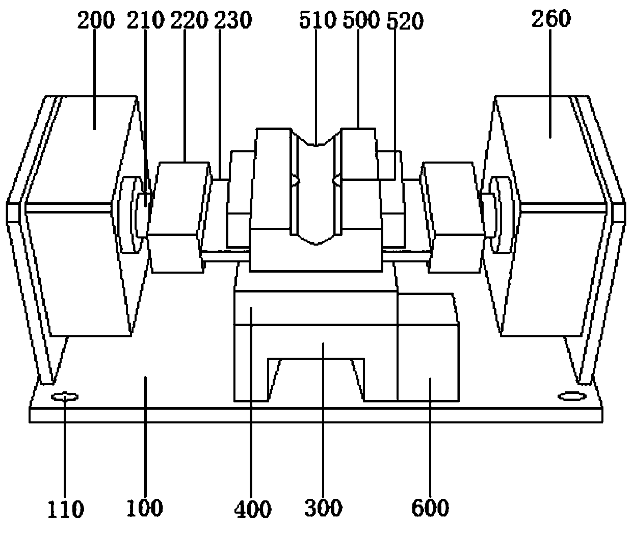
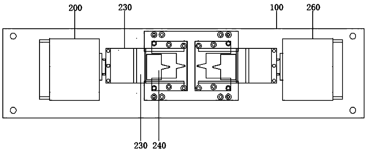
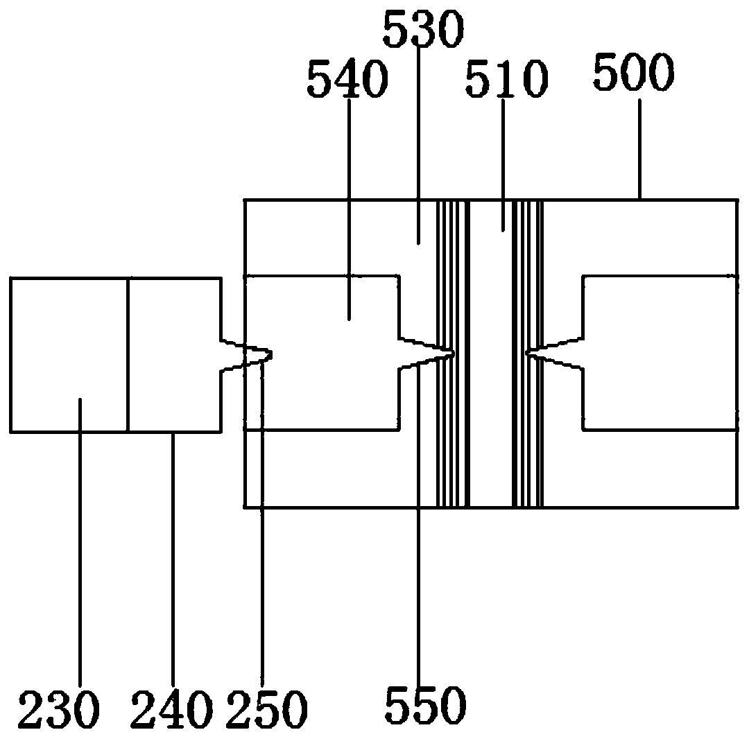
[0023] The present invention provides an integrated equipment for pneumatic forming, scissors and decoating. Through the combined use of accessories, it is convenient for pin positioning, cutting, recycling and decoating effect. The degree of integration is high. Please refer to Figure 1-5 , including the bottom frame 100, the main cylinder 200, the auxiliary cylinder 260, the door frame 300, the top frame 400, the contact plate 500 and the side frame 600;

...


PUM


Abstract

The invention particularly relates to pneumatic forming pin shearing and coating removing integrated equipment which belongs to the technical field of pin correction processing devices. The equipmentcomprises a bottom frame, a main cylinder, an auxiliary cylinder, a gantry, a top frame, a contact plate and a side frame, the top of the bottom frame is fixedly connected with the main air cylinder,the auxiliary air cylinder and the gantry through screws. According to the pneumatic forming, pin shearing and coating removing integrated equipment, the purposes of straightening and forming can be achieved; the limiting is facilitated, a cutting plate controlled by an air cylinder is matched to move; force is applied to the cutting tool carrying a cutting head and a die groove in a die plate; the shearing purpose is achieved; copper wire heads subjected to pin shearing fall into a waste box along a transfer groove; the recycling performance is good, potential safety hazards of waste materials to operators is reduced, at the same time, the side frame is matched, a grinder driven by a built-in motor can be matched to conduct coating removing work on outer portions of pins, and the equipment has the effects of pin limiting, cutting, recycling and coating removing, is high in integration degree, and effectively improves the overall processing efficiency.

Description

technical field [0001] The invention relates to the technical field of calibration feet processing devices, in particular to an integrated device for removing coatings from pneumatic forming and shearing feet. Background technique [0002] A coil usually refers to a ring-shaped wire winding. The most common coil applications are: motors, inductors, transformers, and loop antennas. The coil in the circuit refers to an inductor. , It means that the wires are wound one by one, the wires are insulated from each other, and the insulating tube can be hollow, or it can contain iron core or magnetic powder core, referred to as inductance. [0003] The pin position of the coil needs to be pre-processed. Pins, also called pins, are called Pins in English. They are the connections from the internal circuit of the integrated circuit to the peripheral circuit. All the pins constitute the interface of the chip. A section at the end. [0004] And the pins need to be cut or decoated befor...

Claims


Application Information

Patent Timeline
Patent Type & Authority Applications(China)
IPC IPC(8): H01F41/04
CPCH01F41/04
Inventor 程登峰
Owner WUHAN CHENYANG ELECTRONICS TECH
Why Eureka
Try Eureka