High-voltage generator rectifying device, high-voltage generator and medical equipment
A high-voltage generator and rectifier technology, which is used in output power conversion devices, high-efficiency power electronic conversion, conversion of AC power input to AC power output, etc.
- Summary
- Abstract
- Description
- Claims
- Application Information
AI Technical Summary
Problems solved by technology
Method used
Image
Examples
no. 1 example
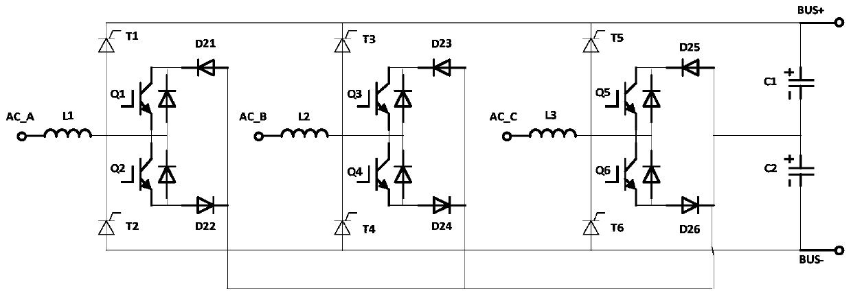
[0050] The first embodiment, such as image 3 As shown, a high-voltage generator rectification device, wherein the three AC potentials of the three-phase power supply are respectively connected to the rectification device through the AC_A input port, the AC_B input port and the AC_C input port. The AC_A input port is connected to the DC power output positive pole through the inductor L1 and the thyristor T1; the AC_A input port is connected to the DC power output negative pole through the inductor L1 and the thyristor T2. A capacitor C1 and a capacitor C2 are connected between the positive output pole of the DC power supply and the negative output pole of the DC power supply. The AC_A input port is connected to the connection point of the capacitor C1 and the capacitor C2 through the IGBT Q1 and the diode D21; the AC_A input port is connected to the connection point of the capacitor C1 and the capacitor C2 through the IGBT Q2 and the diode D22. The AC_B input port is connecte...
no. 2 example
[0056] Second embodiment, such as Figure 9 As shown, a high-voltage generator rectification device, wherein the three AC potentials of the three-phase power supply are respectively connected to the rectification device through the AC_A input port, the AC_B input port and the AC_C input port. The AC_A input port is connected to the DC power output positive pole through the inductor L1 and the thyristor T1; the AC_A input port is connected to the DC power output negative pole through the inductor L1 and the thyristor T2. A capacitor C1 and a capacitor C2 are connected between the positive output pole of the DC power supply and the negative output pole of the DC power supply. The AC_A input port is connected to the connection point of the capacitor C1 and the capacitor C2 through two reversely connected IGBTs Q1 and IGBT Q2 . The AC_B input port is connected to the DC power output positive pole through the inductor L2 and the thyristor T3; the AC_B input port is connected to th...
no. 3 example
[0058] The third embodiment, such as Figure 10 As shown, a high-voltage generator rectification device, wherein the three AC potentials of the three-phase power supply are respectively connected to the rectification device through the AC_A input port, the AC_B input port and the AC_C input port. The AC_A input port is connected to the DC power output positive pole through the inductor L1, the IGBT Q1 and the thyristor T1; the AC_A input port is connected to the DC power output negative pole through the inductor L1, the IGBT Q2 and the thyristor T3. A capacitor C1 and a capacitor C2 are connected between the positive output pole of the DC power supply and the negative output pole of the DC power supply. The cathode of the diode D1 is connected to the connection point of the IGBT Q1 and the thyristor T1; the anode of the diode D1 is connected to the connection point of the capacitor C1 and the capacitor C2. The anode of the diode D2 is connected to the connection point of the ...
PUM
 Abstract
Description
Claims
Application Information
 - R&D
- Intellectual Property
- Life Sciences
- Materials
- Tech Scout
- Unparalleled Data Quality
- Higher Quality Content
- 60% Fewer Hallucinations
Browse by: Latest US Patents, China's latest patents, Technical Efficacy Thesaurus, Application Domain, Technology Topic, Popular Technical Reports.
© 2025 PatSnap. All rights reserved.Legal|Privacy policy|Modern Slavery Act Transparency Statement|Sitemap|About US| Contact US: help@patsnap.com


