Laser cleaning machine for cylindrical nickel screen

A technology of laser cleaning and cleaning mechanism, which is applied in the direction of printing machines, cleaning methods and tools, general parts of printing machinery, etc. It can solve the problems of large floor area of ​​cleaning machines and low cleaning efficiency, so as to reduce floor space, The effect of cost saving and convenient debugging

Active Publication Date: 2020-05-01
NANTONG UNIVERSITY
View PDF12 Cites 2 Cited by
  • Summary
  • Abstract
  • Description
  • Claims
  • Application Information

AI Technical Summary

Problems solved by technology

When the laser cleaning machine of the above technical solution is working, the vertically placed laser tube moves along the axis of the nickel mesh, resulting in an excessively large floor a

Method used


Image

  • Laser cleaning machine for cylindrical nickel screen
  • Laser cleaning machine for cylindrical nickel screen
  • Laser cleaning machine for cylindrical nickel screen

Examples


Example Embodiment

[0025] The present invention will be further described in detail below in conjunction with the drawings.

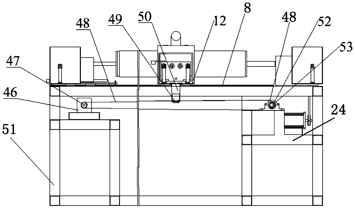
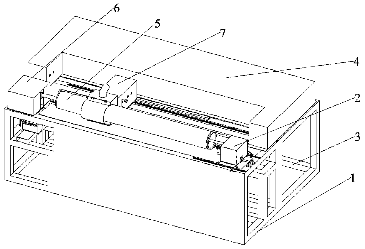
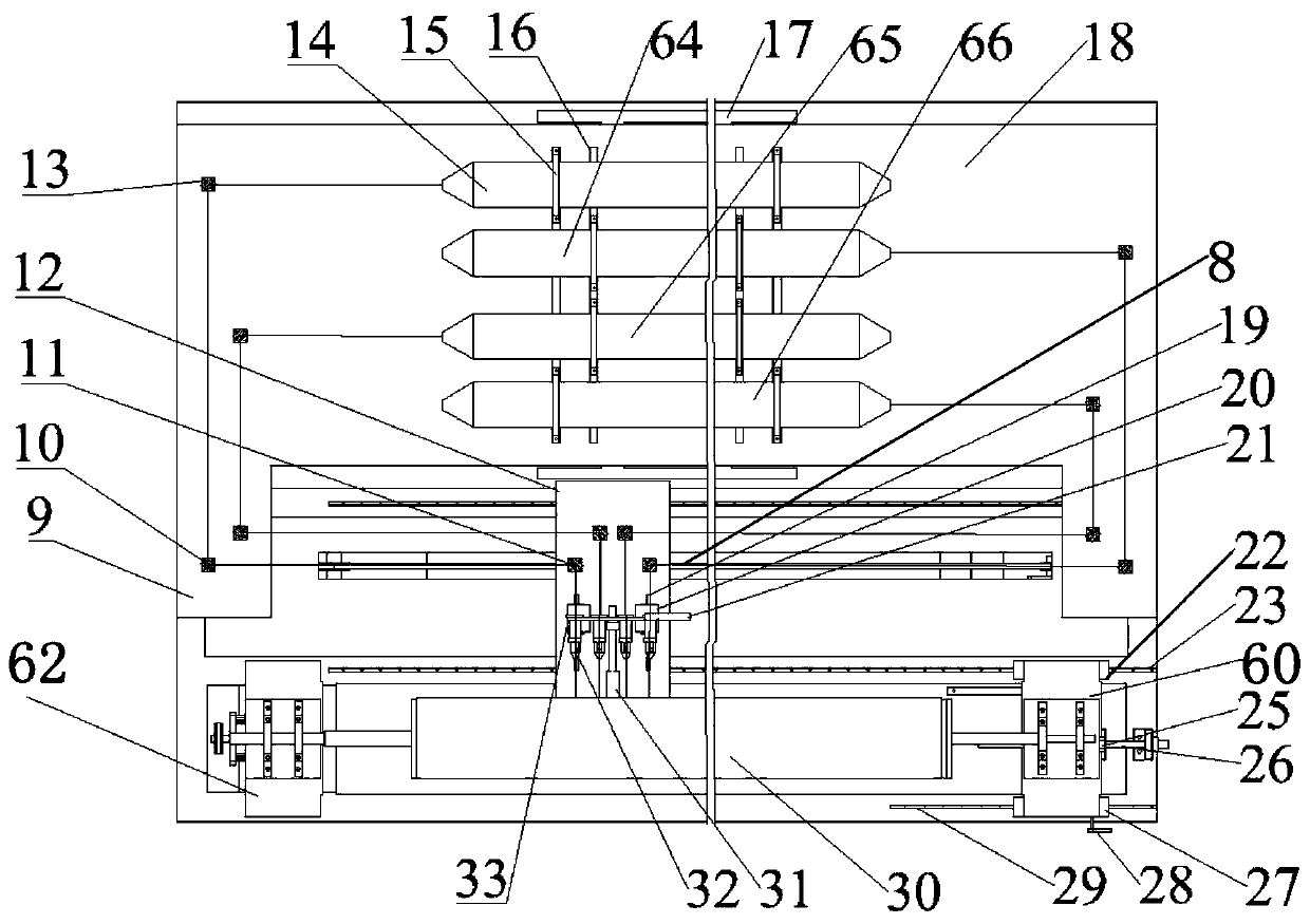
[0026] Such as Figure 1 to Figure 7 As shown, the present invention proposes a cylindrical nickel mesh laser cleaning machine, including the front of the fuselage 1, the rear of the fuselage 3, the cylindrical nickel mesh rotating mechanism 5, the tailstock mechanism 2, the laser emitting mechanism 4, and the motor drive Mechanism 6, cleaning mechanism 7, transmission mechanism; the front of the fuselage 1 is fixedly connected to the rear of the fuselage 3; the cylindrical nickel mesh rotating mechanism 5 and the motor drive mechanism 6 are all set in the front 1 of the fuselage; the tailstock mechanism 2 slides Connected to the front 1 of the fuselage; one end of the cylindrical nickel mesh rotating mechanism 5 is coaxially connected with the motor drive mechanism 6; the other end of the cylindrical nickel mesh rotating mechanism 5 is coaxially connected with the tailstock...


PUM


Abstract

The invention relates to a laser cleaning machine for a cylindrical nickel screen, and belongs to the technical field of laser cleaning devices. The laser cleaning machine comprises a machine body front portion, a machine body rear portion, a cylindrical nickel screen rotating mechanism, a tail bracket mechanism, a laser emission mechanism, a motor driving mechanism, a cleaning mechanism and a transmission mechanism. By using three groups of reflectors, through the reflective cooperation of the reflectors, the directions of the beams emitted by laser tubes are changed. In the cleaning process,the cylindrical nickel screen is rotated simply by moving the cleaning mechanism, and the space occupation of the device is reduced by fixing the laser tubes and changing the arrangement way of the laser tubes. An original arrangement way that the laser tubes are perpendicular to the nickel screen is replaced. The transverse distance between the beam focuses when lasers reach the cylindrical nickel screen is shortened, that is, when the cylindrical nickel screen is cleaned, the cleaning mechanism can move a shorter distance, and by means of the structure, the cleaning efficiency can be effectively improved. By using the cleaning structure which can move independently without moving the laser tubes or a power supply thereof, the load of a motor is greatly reduced, therefore, the motor which has lower technical parameters can be selected, and the cost is saved.

Description

technical field [0001] The invention specifically relates to a cylindrical nickel mesh laser cleaning machine, which belongs to the technical field of laser cleaning equipment. Background technique [0002] Rotary screen printing occupies the main market of textile printing in China. Its key component is seamless nickel rotary screen, referred to as nickel screen, which is usually made by electroforming, and its mesh is hexagonal. The pattern is printed on the nickel mesh by photosensitive method, and the photosensitive adhesive layer can be cleaned after use to realize the recycling of the nickel mesh. Laser technology can be used to remove photosensitive glue. The principle of laser removal of photosensitive glue is to irradiate the laser through optical focusing and then irradiate the part that needs to be cleaned. The laser energy can be highly concentrated in time and space, and the focused laser beam can produce several near the focus Thousands or even tens of thousan...

Claims


Application Information

Patent Timeline
IPC IPC(8): B08B7/00B08B13/00B41F35/00
CPCB08B7/0042B08B13/00B41F35/003B41P2235/12
Inventor 黄明宇薛少兵詹伟郑磊魏言标周倩倪红军
Owner NANTONG UNIVERSITY
Why Eureka
Try Eureka