
3-axis side -view confocal fluorescence endomicroscope

An optical focusing, beam technology, used in microscopes, optics, telescopes, etc., to solve problems such as limited availability

Pending Publication Date: 2020-05-01
THE RGT OF THE UNIV OF MICHIGAN
View PDF5 Cites 3 Cited by
  • Summary
  • Abstract
  • Description
  • Claims
  • Application Information

AI Technical Summary

Problems solved by technology

Because firm contact with tissue is required to couple light, this orientation limits its usefulness in a variety of applications, including when examining the epithelium of small animals

Method used


Image

  • 3-axis side -view confocal fluorescence endomicroscope
  • 3-axis side -view confocal fluorescence endomicroscope
  • 3-axis side -view confocal fluorescence endomicroscope

Examples


Embodiment Construction

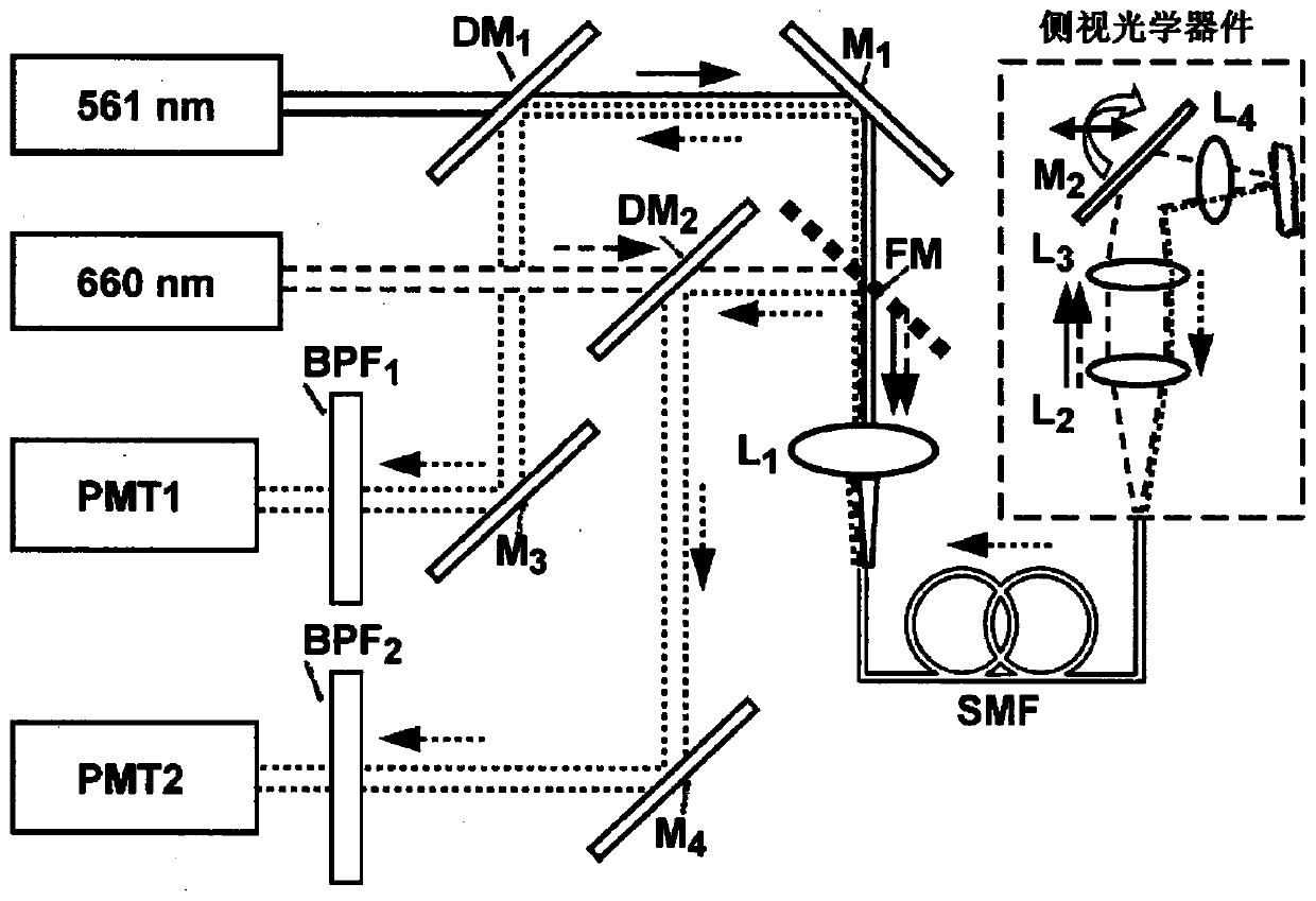
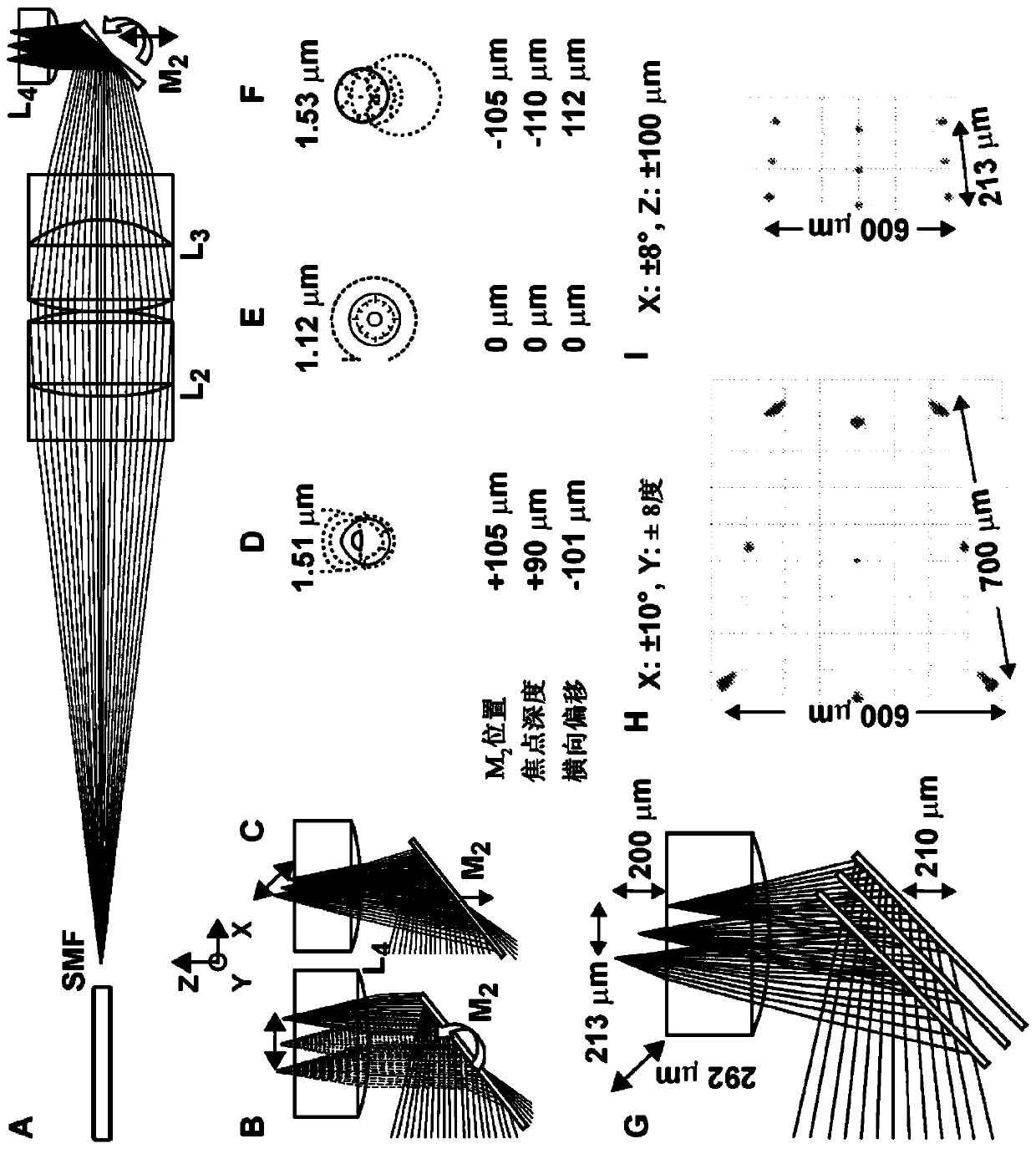
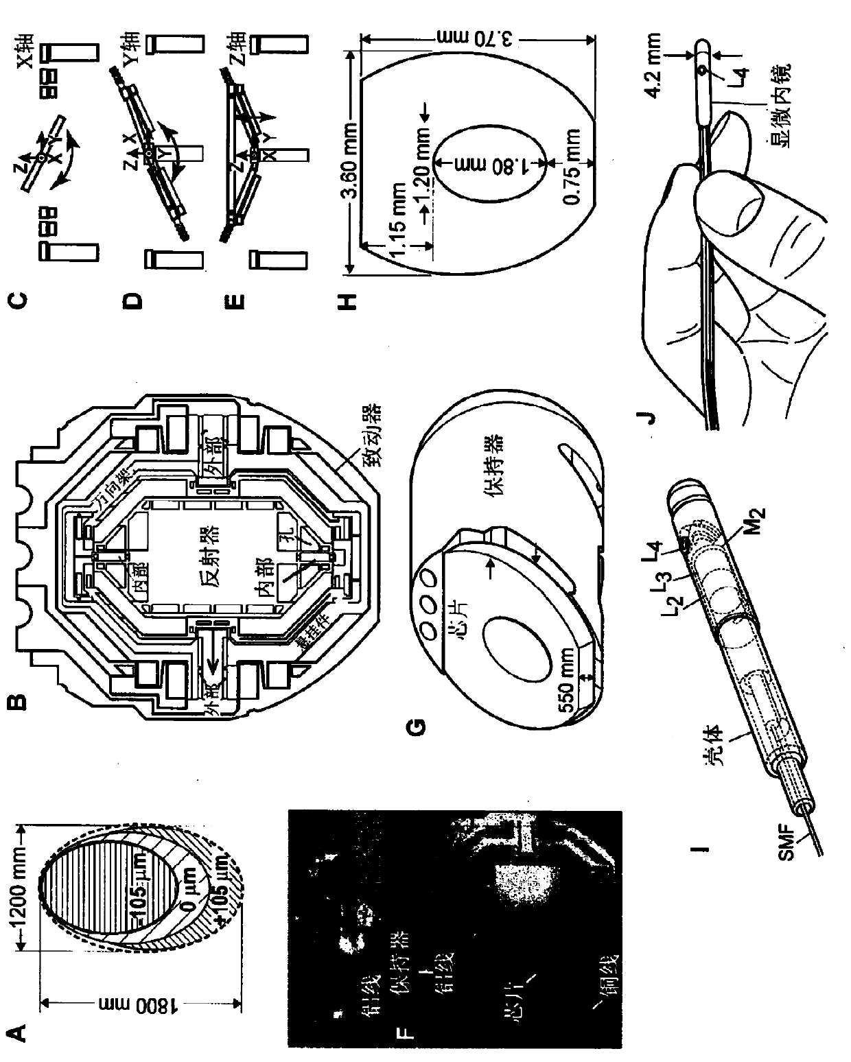
[0035] According to these various embodiments, an optical probe scanning assembly is provided. The optical probe scanning assembly includes a housing having a proximal end configured to receive a fiber optic bundle source and a distal end for positioning at a sample. The housing has a length extending along a longitudinal axis extending from the proximal end to the distal end. An optical focusing assembly is included to focus the output beam from the fiber bundle source along the axial beam path. Downstream of the optical focusing assembly (where downstream refers to a position on the far side or behind in the direction of the output beam) is a 3-axis mirror scanning assembly. The mirror assembly is positioned at an angle relative to the axial beam path such that the output beam is deflected to the transverse axis to emit the output beam from the side of the housing. For example, the lateral beam path may be orthogonal to the axial beam path for emitting the output beam from...


PUM

PropertyMeasurementUnit
Diameteraaaaaaaaaa
Diameteraaaaaaaaaa

Abstract

An optical probe assembly as a confocal endomicroscope includes an optical focusing stage that focuses an output beam onto a sample and a mirror scanning stage that is movable for scanning the outputbeam in both a lateral two dimensional plane and an axial direction, using a side-view configuration. The side-view configuration allows for output beam illumination and fluorescent imaging of the sample with greater imaging resolution and improved access to hard to reach tissue within a subject.

Description

[0001] Cross References to Related Applications [0002] This application is based on 35 U.S.C. §119(e) of a U.S. Provisional Patent Application entitled "3-Axis Side-view Confocal Fluorescence Endomicroscope," filed July 24, 2017 Priority No. 62 / 536,285, the disclosure of which is incorporated herein by reference in its entirety. [0003] Statement of Government Interest [0004] This invention was made with Government support under Grant No. CA142750 awarded by the National Institutes of Health. The government has certain rights in this invention. technical field [0005] The present disclosure relates generally to techniques for imaging tissue using optics, and more particularly, to techniques for allowing two-dimensional (2D) and three-dimensional (3D) imaging using side-looking optics. Background technique [0006] The background description provided herein is for the purpose of generally presenting the context of the disclosure. To the extent described in this Back...

Claims


Application Information

Patent Timeline
IPC IPC(8): G02B21/02G02B21/04G02B23/24
CPCG02B21/0028G02B21/0032G02B21/0076G02B21/02G02B23/243G02B26/0833A61B1/00096A61B1/00172A61B1/00177A61B1/00193A61B1/043A61B1/0623A61B1/0638A61B1/07A61B5/0068A61B5/0071G02B21/0048G02B23/2461
Inventor 托马斯·D·王段西雨李海军
Owner THE RGT OF THE UNIV OF MICHIGAN
Learn More